Pinpoint Test L: The Brake Warning Indicator Is Never/Always On
- L1 CARRY OUT THE INSTRUMENT CLUSTER INDICATOR LAMP CONTROL ACTIVE COMMAND USING THE DIAGNOSTIC TOOL
- Key in ON position.
- Enter the following diagnostic mode on the diagnostic tool: Instrument Cluster Active Command.
- Select the instrument cluster warning lamps and chime active command. Trigger the all lamps active command on and off. Observe the brake warning indicator.
- Does the brake warning indicator illuminate when triggered on and turn off when triggered off?
- Yes
: GO to L2.
- No
: GO to L13.
- L2 CHECK THE PARKING BRAKE SWITCH PID
- Enter the following diagnostic mode on the diagnostic tool: Parking Brake Switch PID.
- Monitor the instrument cluster parking brake switch PID while applying and releasing the parking brake.
- Does the PID agree with the parking brake position?
- Yes
: GO to L8.
- No
: If the PID indicates that the parking brake is always applied, GO to L3.
- If the PID indicates that the parking brake is always never applied, GO to L5.
- L3 CHECK THE PARKING BRAKE SWITCH (INDICATOR ALWAYS ON)
- Disconnect: Parking Brake Switch C2015.
- Observe the brake warning indicator.
- Does the brake warning indicator continue to illuminate?
- Yes
: GO to L4.
- No
: INSTALL a new parking brake switch. TEST the system for normal operation.
- L4 CHECK CIRCUIT 162 (LG/RD) FOR A SHORT TO GROUND
- Key in OFF position.
- Disconnect: Instrument Cluster C220b.
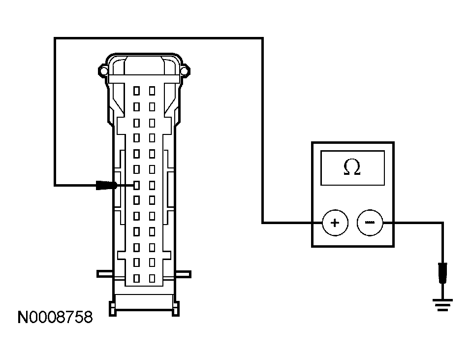
- Measure the resistance between the instrument cluster C220b pin 7, circuit 162 (LG/RD), harness side and ground.
 Courtesy of FORD MOTOR CO.
- Is the resistance greater than 10,000 ohms?
- Yes
: GO to L13.
- No
: REPAIR the circuit. TEST the system for normal operation.
- L5 CHECK THE PARKING BRAKE SWITCH (INDICATOR INOPERATIVE)
- Disconnect: Parking Brake Switch C2015.
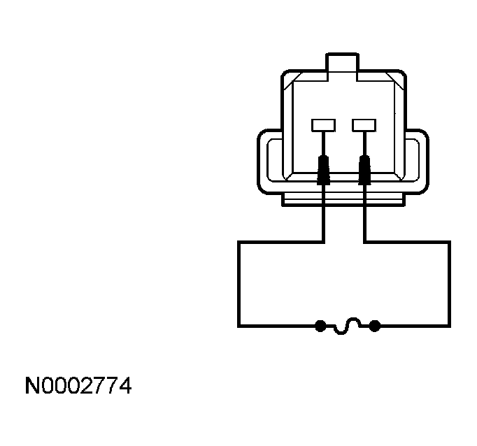
- Connect a fused (5A) jumper wire between the parking brake switch C2015 pin 2, circuit 162 (LG/RD), harness side and the parking brake switch C2015 pin 1, circuit 57 (BK), harness side.
 Courtesy of FORD MOTOR CO.
- Does the brake warning indicator illuminate?
- Yes
: INSTALL a new parking brake switch. TEST the system for normal operation.
- No
: REMOVE the jumper wire. GO to L6.
- L6 CHECK CIRCUIT 57 (BK) FOR AN OPEN
- Key in OFF position.
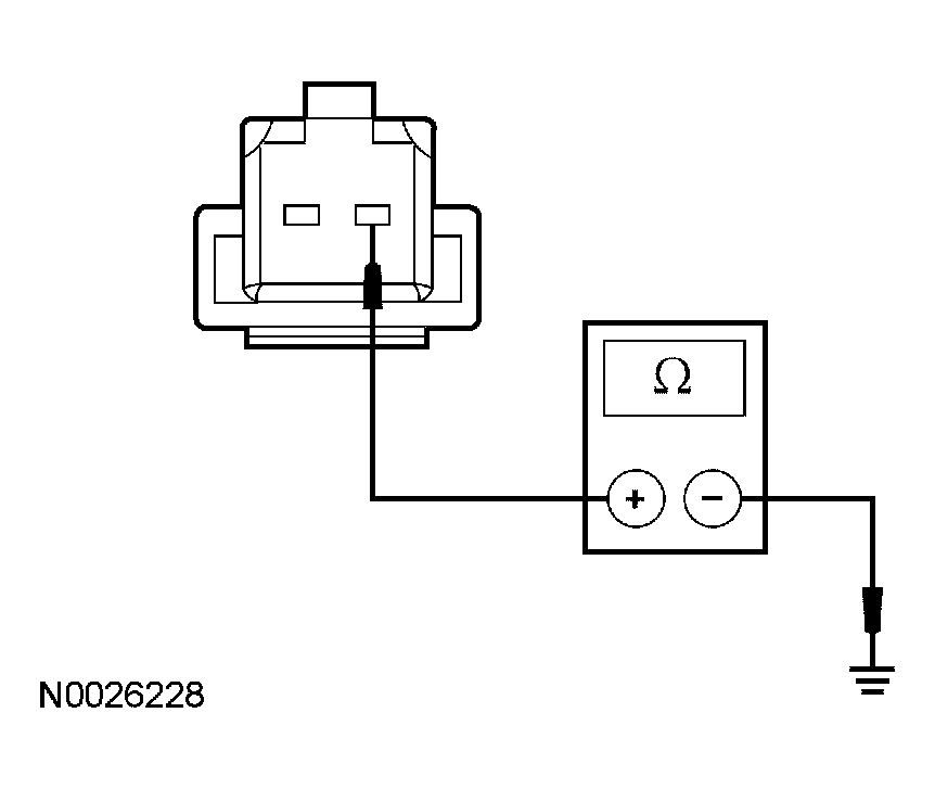
- Measure the resistance between the parking brake switch C2015 pin 1, circuit 57 (BK), harness side and ground.
 Courtesy of FORD MOTOR CO.
- Is the resistance less than 5 ohms?
- Yes
: GO to L7.
- No
: REPAIR the circuit. TEST the system for normal operation.
- L7 CHECK CIRCUIT 162 (LG/RD) FOR AN OPEN
- Disconnect: Instrument Cluster C220b.
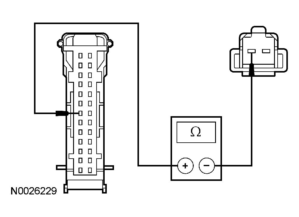
- Measure the resistance between the instrument cluster C220b pin 7, circuit 162 (LG/RD), harness side and the parking brake switch C2015 pin 2, circuit 162 (LG/RD), harness side.
 Courtesy of FORD MOTOR CO.
- Is the resistance less than 5 ohms?
- Yes
: GO to L13.
- No
: REPAIR the circuit. TEST the system for normal operation.
- L8 CHECK THE ANTI-LOCK BRAKE SYSTEM (ABS) MODULE OPERATION
- Key in OFF position.
- Disconnect: Brake Fluid Level Switch C124.
- Key in ON position.
- Observe the brake warning indicator after the instrument cluster proves out.
- Connect a fused (10A) jumper wire between the brake fluid level switch C124 pin 3, circuit 531 (DG/YE), harness side and the brake fluid level switch C124 pin 2, circuit 512 (TN/LG), harness side.
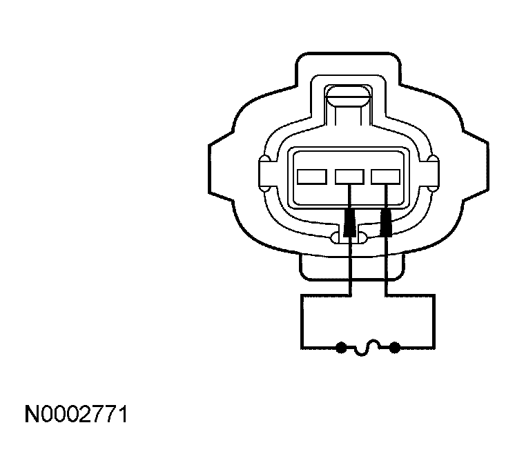 Courtesy of FORD MOTOR CO.
- Does the brake warning indicator illuminate with the brake fluid level switch disconnected and turn off when the jumper wire is in place?
- Yes
: REMOVE the jumper wire. GO to L9.
- No
: REMOVE the jumper wire. GO to L10.
- L9 CHECK CIRCUIT 57 (BK) FOR AN OPEN
- Key in OFF position.
- Measure the resistance between the brake fluid level switch C124 pin 1, circuit 57 (BK), harness side and ground.
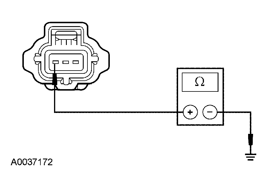 Courtesy of FORD MOTOR CO.
- Is the resistance less than 5 ohms?
- Yes
: INSTALL a new brake fluid level switch. REFER to HYDRAULIC BRAKE ACTUATION
. TEST the system for normal operation.
- No
: REPAIR the circuit. TEST the system for normal operation.
- L10 CHECK CIRCUIT 531 (DG/YE) AND CIRCUIT 512 (TN/LG) FOR AN OPEN
- Key in OFF position.
- Disconnect: ABS Module C135.
- Measure the resistance between the ABS module C135 pin 8, circuit 512 (TN/LG), harness side and the brake fluid level switch C124 pin 2, circuit 512 (TN/LG), harness side; and between the ABS module C135 pin 9, circuit 531 (DG/YE), harness side and the brake fluid level switch C124 pin 3, circuit 531 (DG/YE), harness side.
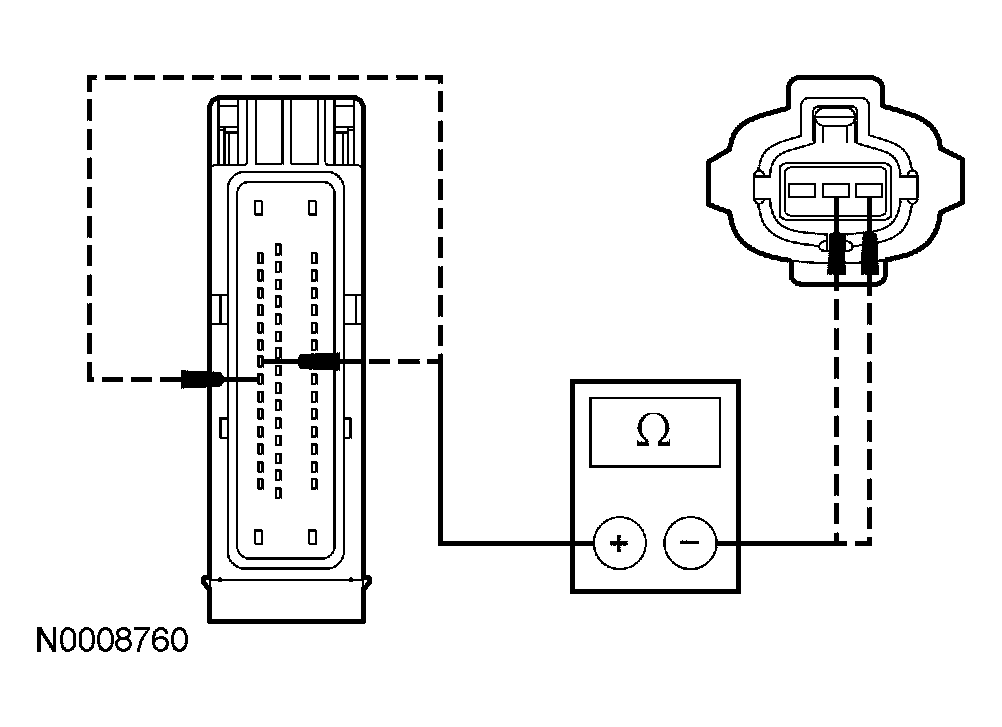 Courtesy of FORD MOTOR CO.
- Are the resistances less than 5 ohms?
- Yes
: GO to L11.
- No
: REPAIR the circuit in question. TEST the system for normal operation.
- L11 CHECK CIRCUIT 531 (DG/YE) AND CIRCUIT 512 (TN/LG) FOR A SHORT TO GROUND
- Measure the resistance between the ABS module C135 pin 8, circuit 512 (TN/LG), harness side and ground; and between the ABS module C135 pin 9, circuit 531 (DG/YE), harness side and ground.
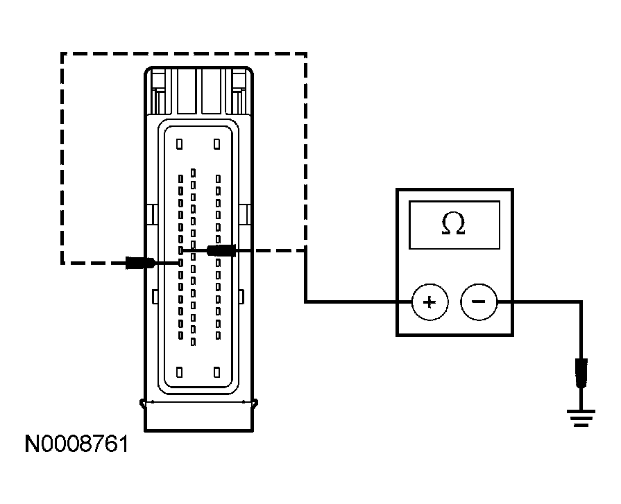 Courtesy of FORD MOTOR CO.
- Are the resistances greater than 10,000 ohms?
- Yes
: GO to L12.
- No
: REPAIR the circuit in question. TEST the system for normal operation.
- L12 CHECK FOR CORRECT ABS MODULE OPERATION
- Disconnect the ABS module connector.
- Check for:
- corrosion
- pushed-out pins
- Correct the ABS module connector and make sure it seats correctly.
- Operate the system and verify that the concern is still present.
- Is the concern still present?
- Yes
: INSTALL a new ABS module. REFER to ANTI-LOCK CONTROL
. TEST the system for normal operation.
- No
: The system is operating correctly at this time. The concern may have been caused by a loose or corroded connector.
- L13 CHECK FOR CORRECT INSTRUMENT CLUSTER OPERATION
- Disconnect all the instrument cluster connectors.
- Check for:
- corrosion
- pushed-out pins
- Connect all the instrument cluster connectors and make sure they seat correctly.
- Operate the system and verify that the concern is still present.
- Is the concern still present?
- Yes
: INSTALL a new instrument cluster. REFER to INSTRUMENT CLUSTER . TEST the system for normal operation.
- No
: The system is operating correctly at this time. The concern may have been caused by a loose or corroded connector.