Pinpoint Test G: A Single Illumination Source Is Inoperative - Door Lock Control Switches
- G1 VERIFY THE POWER DOOR LOCK OPERATION
- Key in ON position.
- Operate and verify power door lock operation.
- Do the power door locks operate correctly?
- G2 CHECK POWER TO THE WINDOW CONTROL SWITCH - CIRCUIT 194 (PK)
- Key in OFF position.
- Disconnect: Door Lock Control Switch C605 (RH) or C505 (LH).
- Key in ON position.
- Measure the voltage between the door lock control switch C505 (LH) or C605 (RH) pin 5, circuit 194 (PK), harness side and ground.
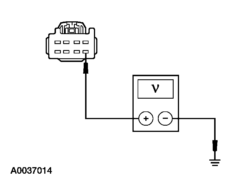 Courtesy of FORD MOTOR CO.
- Is the voltage greater than 10 volts?
- Yes
: GO to G3.
- No
: REPAIR the circuit. TEST the system for normal operation.
- G3 CHECK CIRCUIT 57 (BK) FOR AN OPEN
- Key in OFF position.
- Measure the resistance between the door lock control switch C505 (LH) or C605 (RH) pin 1, circuit 57 (BK), harness side and ground.
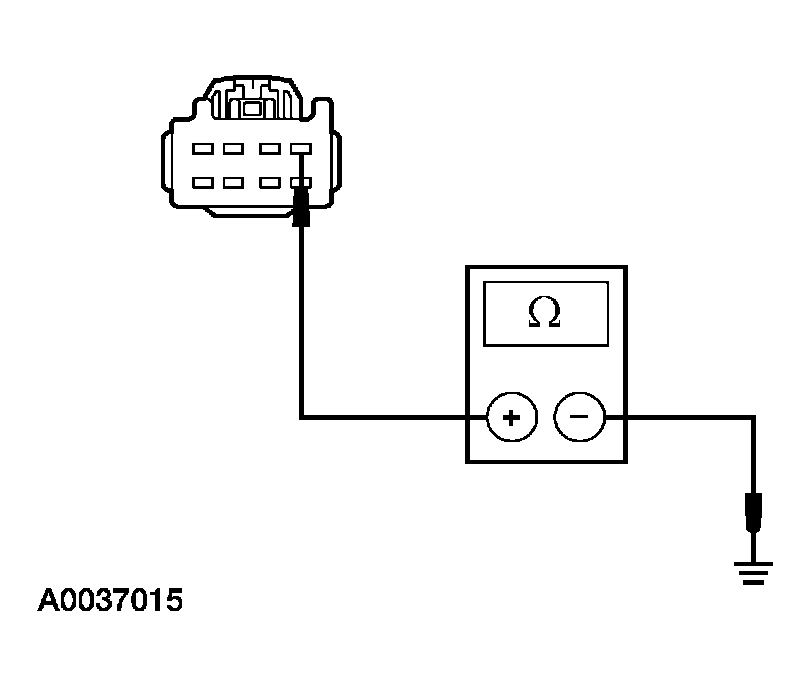 Courtesy of FORD MOTOR CO.
- Is the resistance less than 5 ohms?