Pinpoint Test R: The Reversing Lamps Are Inoperative
- R1 CHECK THE VOLTAGE TO THE DTR SENSOR (A/T) OR THE REVERSING LAMP SWITCH (M/T)
- Key in OFF position.
- Disconnect: DTR Sensor C167 (A/T).
- Disconnect: Reversing Lamp Switch C169 (M/T).
- Key in ON position.
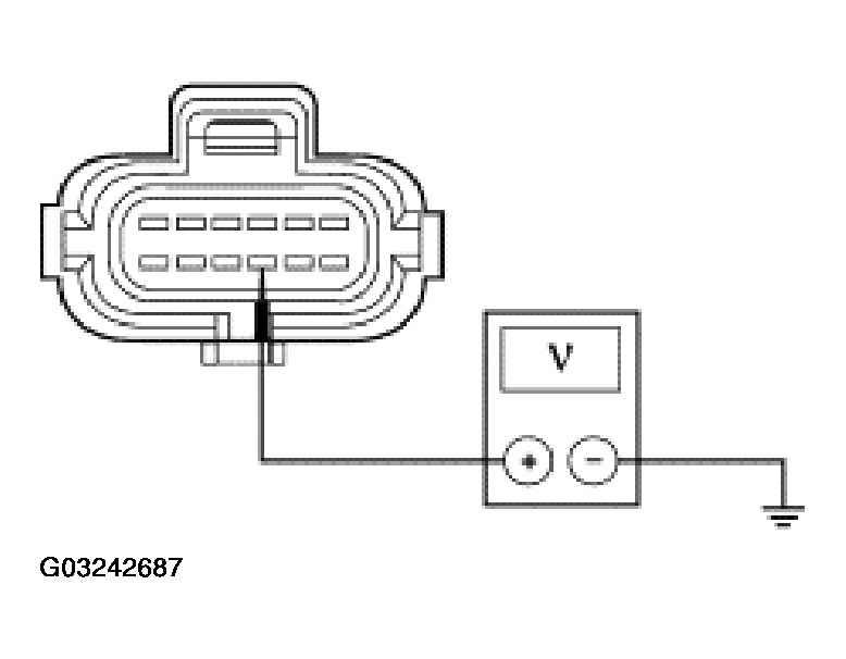
- If equipped with A/T, measure the voltage between DTR sensor C167 Pin 9, Circuit 1087 (OG), harness side and ground.
 Courtesy of FORD MOTOR CO.
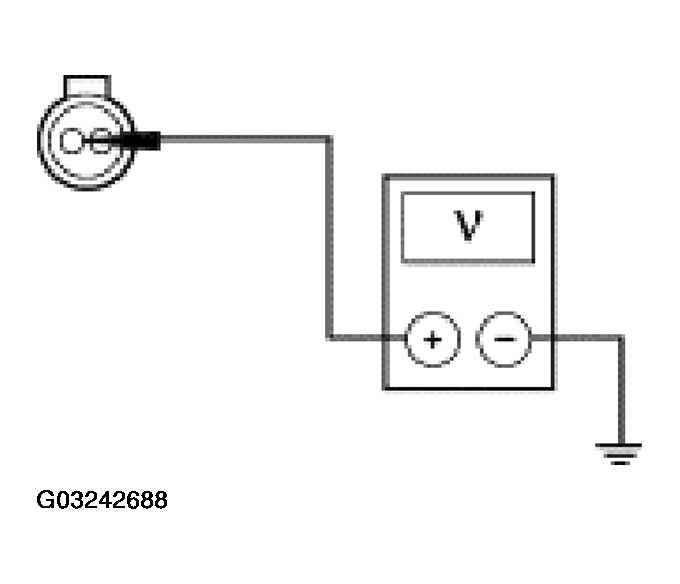
- If equipped with M/T, measure the voltage between reversing lamp switch C169, Circuit 1087 (OG), harness side and ground.
 Courtesy of FORD MOTOR CO.
- Is the voltage greater than 10 volts?
- Yes:
GO to R2.
- No:
REPAIR the circuit. TEST the system for normal operation.
- R2 CHECK CIRCUIT 140 (BK/PK) FOR OPEN
- Key in OFF position.
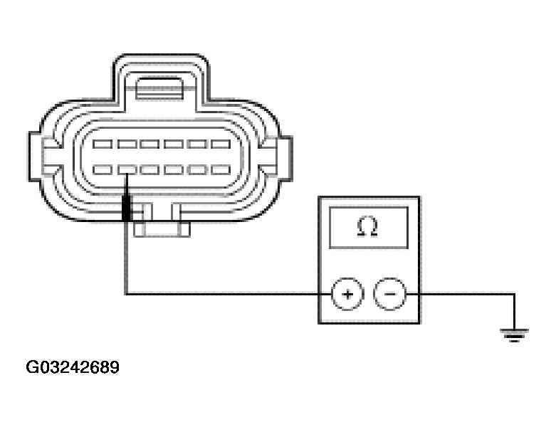
- If equipped with A/T, measure the resistance between DTR sensor C167 Pin 11, Circuit 140 (BK/PK), harness side and ground.
 Courtesy of FORD MOTOR CO.
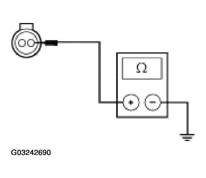
- If equipped with M/T, measure the resistance between reversing lamp switch C169, Circuit 140 (BK/PK), harness side and ground.
 Courtesy of FORD MOTOR CO.
- Is the resistance less than 5 ohms?
- Yes:
INSTALL a new DTR sensor (A/T) or reversing lamp switch (M/T); REFER to AUTOMATIC TRANSAXLE/TRANSMISSION
, MANUAL TRANSAXLE-T50D
or MANUAL TRANSAXLE-TR3650
. TEST the system for normal operation.
- No:
GO to R3.
- R3 CHECK REVERSING LAMPS GROUND
- Disconnect: Inoperative Reversing Lamp.
- Measure the resistance between LH reversing lamp C451, Circuit 1205 (BK), or RH reversing lamp C461, Circuit 1205 (BK), harness side and ground.
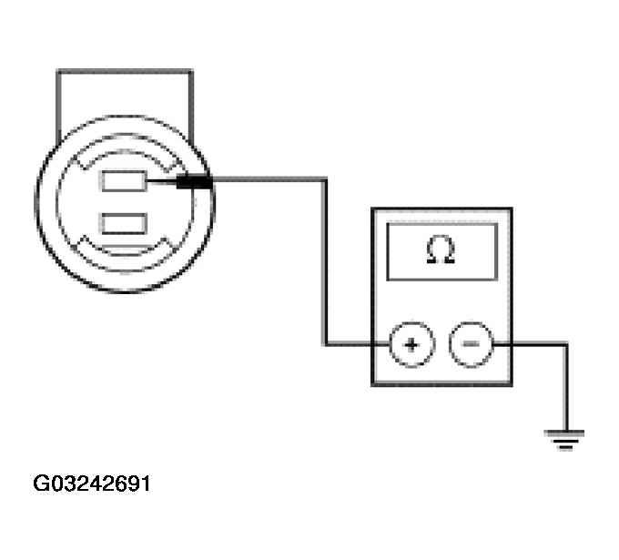 Courtesy of FORD MOTOR CO.
- Is the resistance less than 5 ohms?
- Yes:
REPAIR Circuit 140 (BK/PK) for open. TEST the system for normal operation.
- No:
REPAIR the circuit. TEST the system for normal operation.