Test A: All Instrument Cluster Displays Erratic/Inoperative: ZX2
- Turn ignition switch to LOCK position. Check METER fuse (10-amp). See Figure. If fuse is not blown, go to next step. If fuse is blown, replace fuse. Turn ignition switch to ON position and recheck fuse. If fuse blows again, check and repair short to ground in Black/Yellow wire(s) between central junction box and instrument cluster. See WIRING DIAGRAMS . Retest system operation.
- Turn ignition switch to ON position. Measure voltage between ground and top terminal of METER fuse holder (toward ASC fuse). See Figure. If voltage is more than 10 volts, reinstall fuse and go to next step. If voltage is less than 10 volts, repair power feed circuit to METER fuse. For circuit identification, see POWER DISTRIBUTION in appropriate SYSTEM WIRING DIAGRAMS article in ELECTRICAL. Retest system operation.
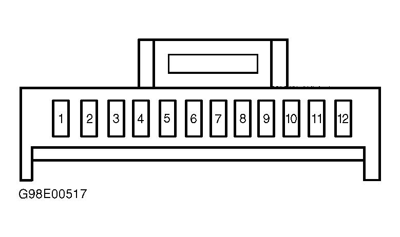
- Turn ignition switch to LOCK position. Remove instrument cluster. See INSTRUMENT CLUSTER under REMOVAL & INSTALLATION. Disconnect instrument cluster harness connectors. Turn ignition switch to ON position. Measure voltage between ground and instrument cluster 10-pin harness connector C254 terminal No. 6 (Black/Yellow wire). See Figure. Measure voltage between ground and Black instrument cluster 12-pin harness connector C252 terminal No. 12 (Black/Yellow wire). See Figure. Measure voltage between ground and White instrument cluster 12-pin harness connector C258 terminals No. 4 and 12 (Black/Yellow wires). See Fig 1. If voltage is more than 10 volts at each terminal, go to next step. If voltage is less than 10 volts at any terminal(s), repair open in Black/Yellow wire(s). See WIRING DIAGRAMS . Retest system operation.
- Turn ignition switch to LOCK position. Measure resistance between ground and instrument cluster 10-pin harness connector C254 terminal No. 5 (Black/Green wire). Measure resistance between ground and Black instrument cluster 12-pin harness connector C252 terminals No. 8 (Black wire) and No. 11 (Blue wire). Measure resistance between ground and White instrument cluster 12-pin harness connector C258 terminal No. 6 (Black/Green wire). If resistance is less than 5 ohms at each terminal, replace instrument cluster printed circuit and gauge contact clips. See PRINTED CIRCUIT under REMOVAL & INSTALLATION. Retest system operation. If resistance is more than 5 ohms at any terminal, repair open in appropriate wire(s). See WIRING DIAGRAMS . Retest system operation.
 Courtesy of FORD MOTOR CO.