Removal and Installation
- Park the wiper arms in the highest position on the glass.
- Disconnect negative battery cable.
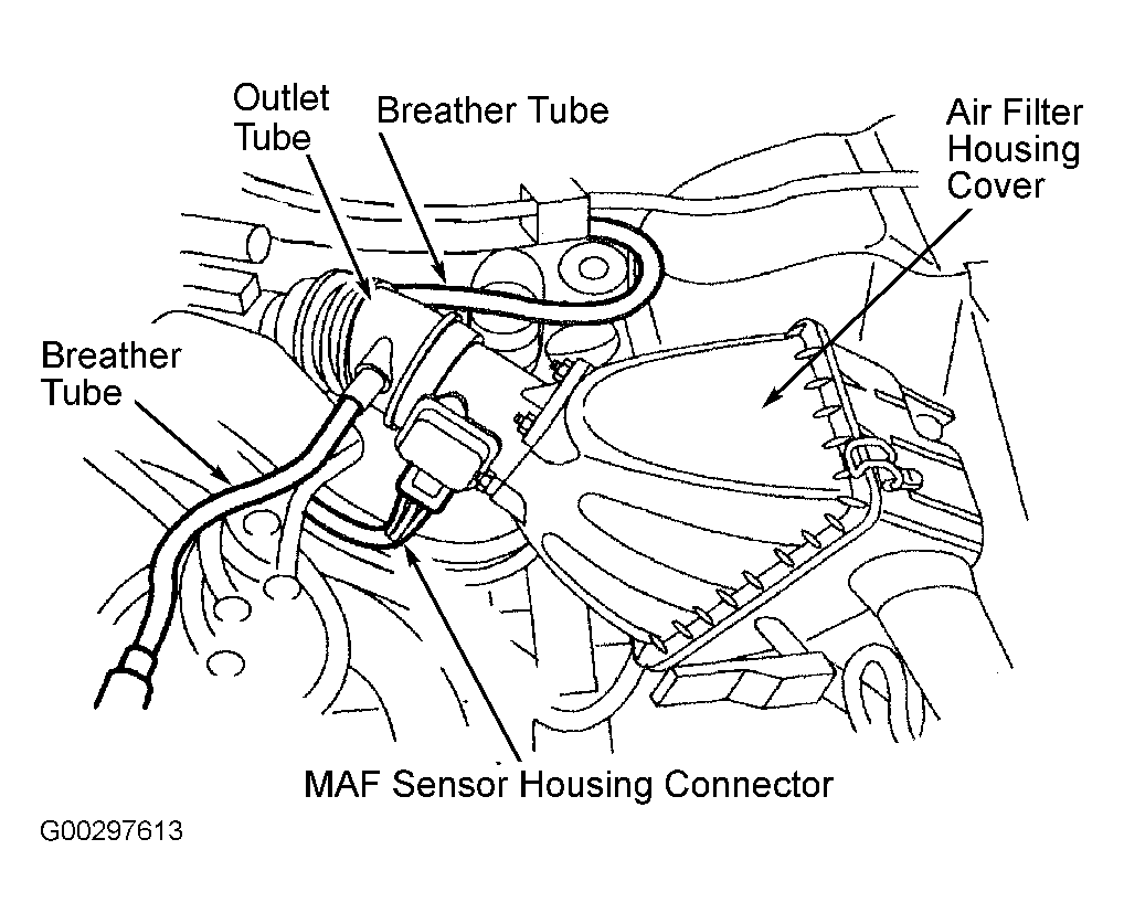
- Disconnect the Mass Air Flow (MAF) sensor and the breather tubes. See Fig 1.
- Disconnect the outlet tube from the throttle body. See Fig 1.
- Remove the engine air cleaner housing cover and position it aside. See Fig 1.
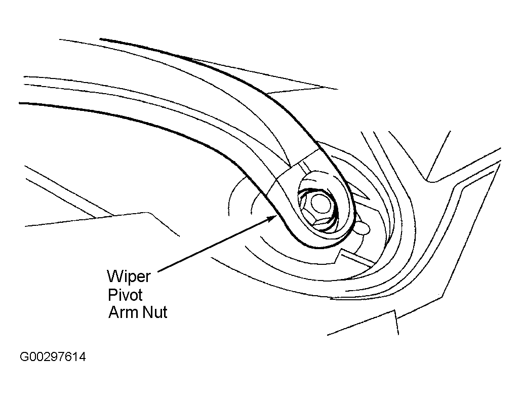
- Remove the wiper arm pivot nut covers, nuts and the wiper pivot arms. See Fig 2.
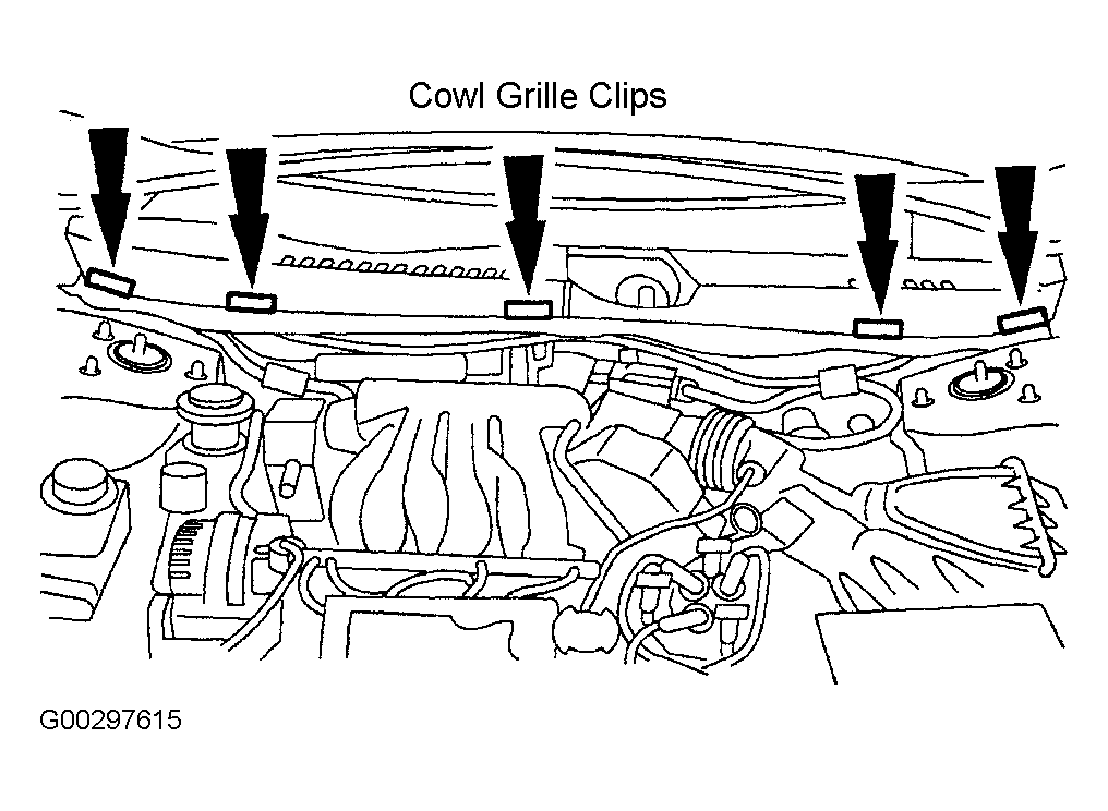
- Remove the cowl grille clips. See Fig 3.
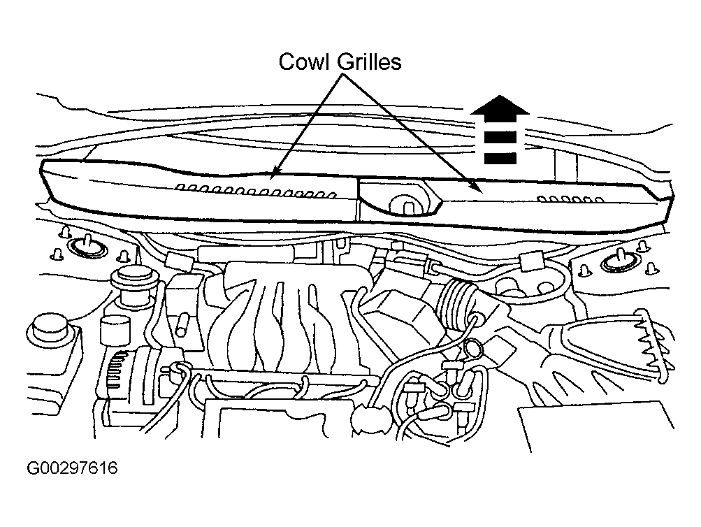
- Remove the cowl top vent grilles. See Fig 4.
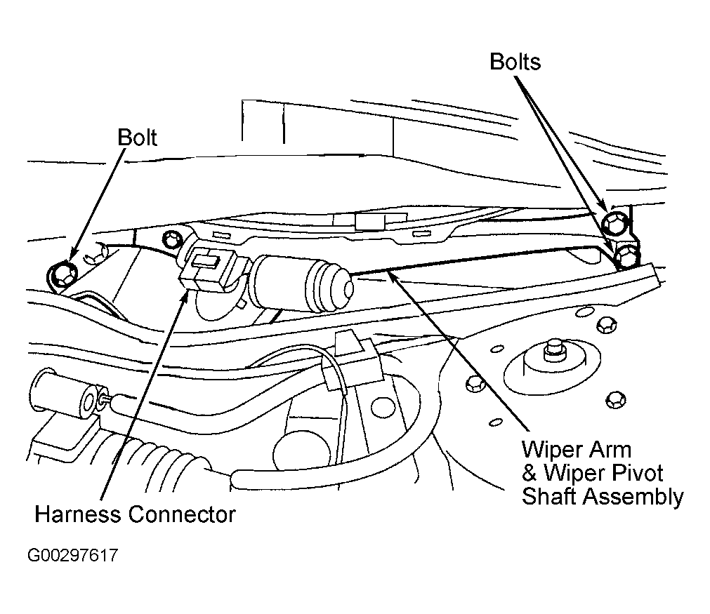
- Remove the four bolts, wiper mounting arm and wiper pivot shaft assembly. Disconnect the harness connector. See Fig 5.
- Remove the brake master cylinder. See MASTER CYLINDER
.
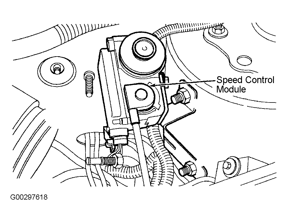
- Disconnect the speed control module harness connector. Remove the speed control module mounting nuts. Position the module and bracket out of the way. See Fig 6.
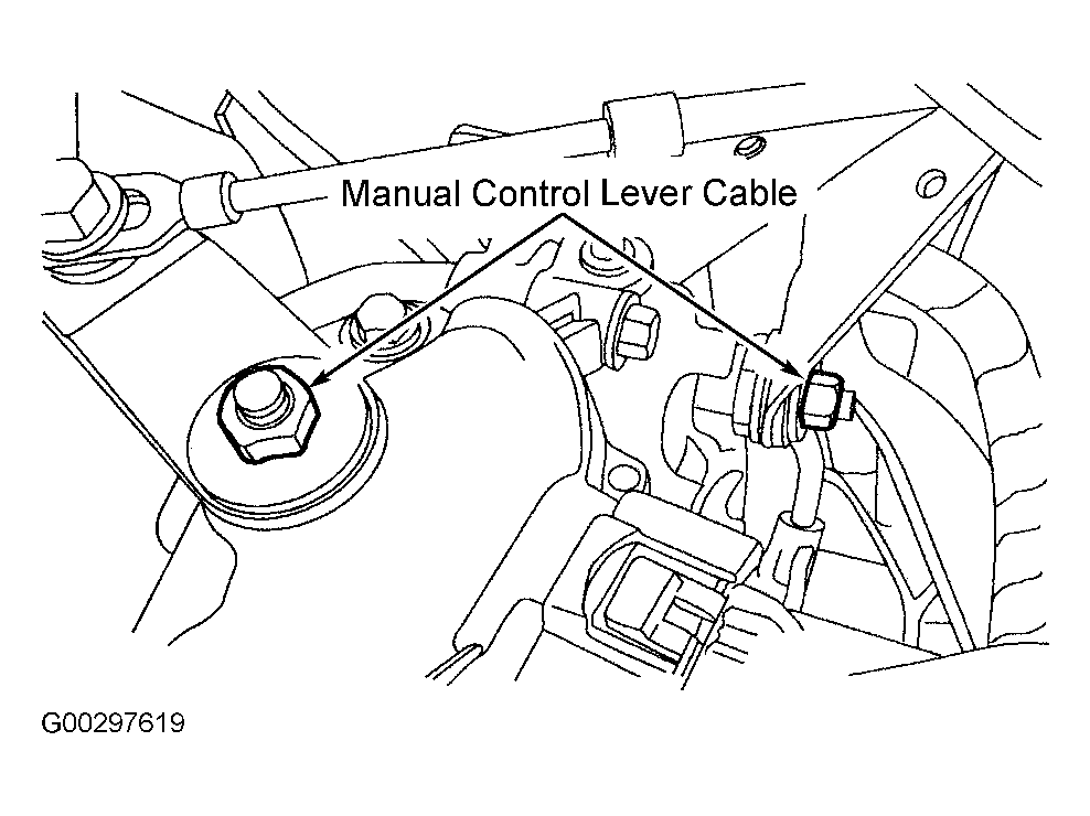
- Disconnect the manual control lever cable from the Transmission Range Sensor (TRS) and remove the manual cable bracket nut. See Fig 7.
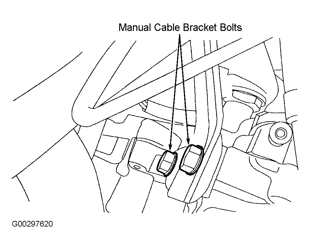
- Remove the manual cable bracket bolts and position the bracket out of the way. See Fig 8.
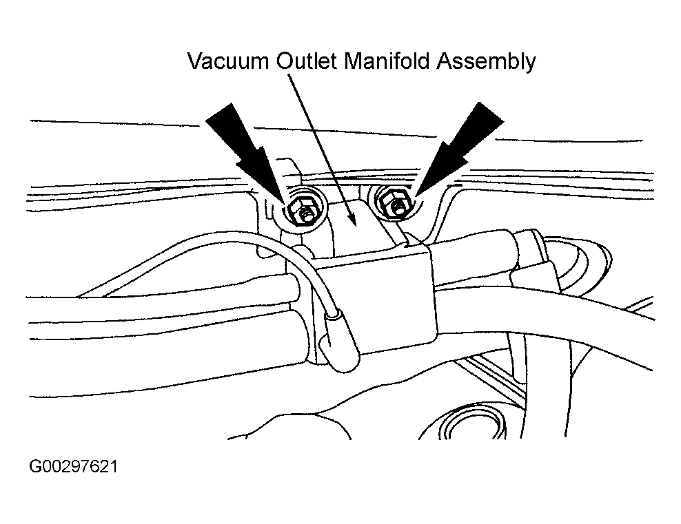
- Remove the vacuum outlet manifold assembly. See Fig 9.
- Detach the vacuum booster check valve.
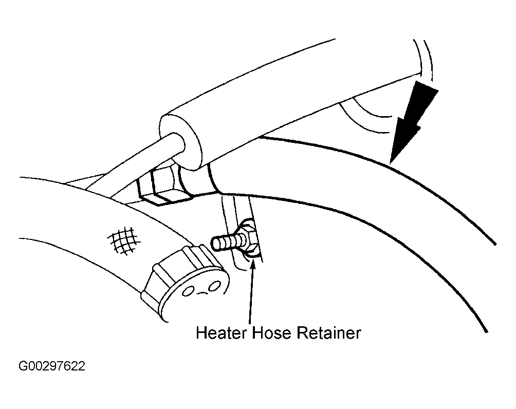
- Remove and discard the nut, and detach the heater hose retainer. See Fig 10. Position the hose out of the way.
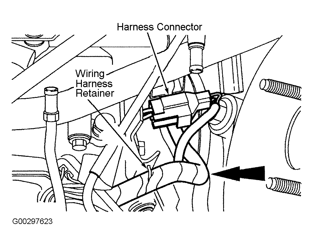
- Detach the wiring harness and the harness connector retainers. Position the wiring harness out of the way. It is not necessary to disconnect the harness connector. See Fig 11.
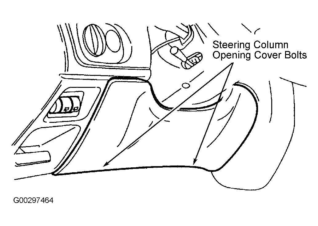
- Remove two bolts and the steering column opening cover. See Fig 12.
- Disconnect the booster push rod. Disconnect the harness connector. Remove the push rod retainer. Slide the push rod off the pin and remove the stoplight switch, the washer, and the bushing.
- Remove the brake booster. Discard mounting nuts.
- To install, reverse the removal procedure. Use NEW nuts. Tighten all fasteners to specification. See TORQUE SPECIFICATIONS . Bleed brakes. See BLEEDING BRAKE SYSTEM
.
 Courtesy of FORD MOTOR CO.
 Courtesy of FORD MOTOR CO.
 Courtesy of FORD MOTOR CO.
 Courtesy of FORD MOTOR CO.
 Courtesy of FORD MOTOR CO.
 Courtesy of FORD MOTOR CO.
 Courtesy of FORD MOTOR CO.
 Courtesy of TECH-COR, INC.
 Courtesy of FORD MOTOR CO.
 Courtesy of FORD MOTOR CO.
 Courtesy of FORD MOTOR CO.
 Courtesy of FORD MOTOR CO.