Test H: Incorrect Oil Pressure Gauge Indication
- Start engine and increase RPM to 2500 while observing the oil pressure gauge. If oil pressure gauge reading increases with engine RPM, system is operating correctly and no further testing is needed. If oil pressure gauge does not indicate pressure, go to step 3. If oil pressure gauge indicates pressure but does not increase with engine RPM, go to next step.
- Start engine and observe tachometer operation. If tachometer operates correctly, go to step 7. If tachometer does not operate correctly, go to testE .
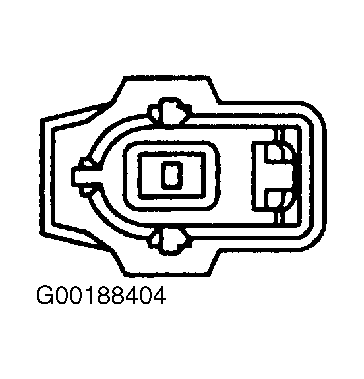
- Turn ignition to LOCK. Disconnect engine oil pressure switch connector C954. See Fig 1. Connect a 10-amp fused jumper wire between harness connector C954 (Black/Orange wire) and ground. Turn ignition ON. Observe oil pressure gauge with jumper wire connected and not connected. If gauge reads LOW with jumper wire connected and NORMAL (middle) with jumper wire not connected, go to next step. If gauge does not read as stated, go to step 5.
- Check engine oil pressure with a manual gauge. See appropriate 2.0L 4-CYL article in ENGINE . If oil pressure is within specifications, replace switch and test system operation. If oil pressure is not within specifications, repair engine lubrication mechanical problem to correct oil pressure concern.
- Turn ignition to LOCK position. Disconnect instrument cluster connector C853 and oil pressure switch connector C954. Measure resistance between C853 terminal No. 3 (Black/Orange wire) and C954 (Black/Orange wire). See Fig 1 and Fig 2
. Also measure resistance between C853 terminal No. 3 and ground. If resistance is less than 5 ohms between C853 and C954, and greater than 10k/ohms between C853 and ground, go to next step. If resistance is not as specified, repair open or short to ground between cluster and switch.
- Turn ignition ON. Measure voltage between harness connector C853 terminal No. 3 (Black/Orange wire) and ground. If no voltage is present, go to next step. If any voltage is present, repair short to power in Black/Orange wire.
- Turn ignition switch to LOCK position. Check for corrosion, pushed out pins and connectors that are not connected properly. Repair any damage found and reconnect any loose connectors. Operate system. If problem still exists, replace instrument cluster. See INSTRUMENT CLUSTER under REMOVAL & INSTALLATION. Configure replacement instrument cluster, see MODULE COMMUNICATIONS NETWORK
article. If problem does not exist, system is operating properly at this time. Clear any DTCs and retest.
 Courtesy of FORD MOTOR CO.
 Courtesy of FORD MOTOR CO.