Test A: No Scan Tool Communication With Instrument Cluster (HEC)
- Turn ignition switch to LOCK position. Disconnect HEC harness connector C220c. Turn ignition switch to ON position. Measure voltage between ground and HEC harness connector C220c terminals No. 11 (Light Green/Orange wire), No. 12 (Black/Light Green wire), No. 19 (Black/Pink wire) and No. 20 (Red/Yellow wire). See Fig 1. If battery voltage is present, go to next step. If battery voltage is not present, repair open in appropriate wire. See WIRING DIAGRAMS . Retest system operation.
- Turn ignition switch to LOCK position. Measure resistance between ground and HEC harness connector C220c terminals No. 13 (Pink/Orange wire) and No. 15 (Black wire). See Fig 1. If resistance is 5 ohms or less, repair module communications concern. See MODULE COMMUNICATIONS NETWORK - EXCURSION & F250-F550 SUPER DUTY PICKUPS
article. If resistance is more than 5 ohms, repair open in appropriate wire. See WIRING DIAGRAMS . Retest system operation.
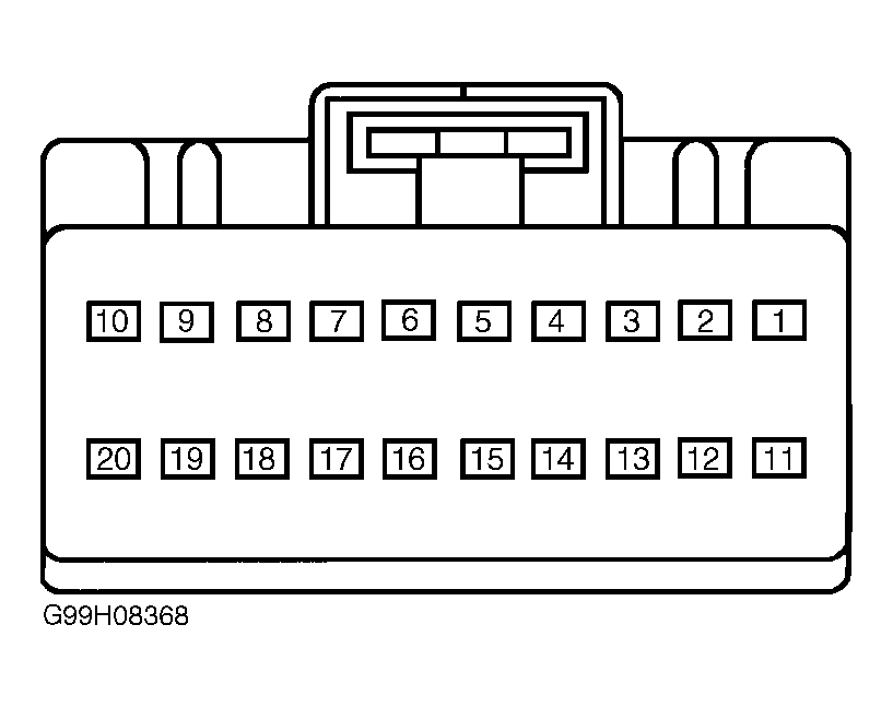 Courtesy of FORD MOTOR CO.