Test H: Speedometer Is Inoperative Or Inaccurate
- Turn ignition switch to RUN position. Using New Generation Star (NGS) tester, select instrument cluster speedometer active command. Trigger, observe and scroll speedometer at 10% increments. Speedometer should increase 10 MPH with every 10% increment increase. If speedometer operates as specified, go to next step. If speedometer does not operate as specified, go to step 4.
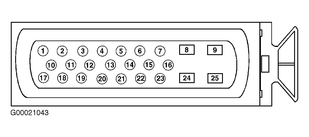
- Turn ignition switch to LOCK position. Disconnect instrument cluster harness connector C220b. Disconnect 4WABS control module harness connector C135. Measure resistance in Gray/Black wire between the instrument cluster harness connector C220b terminal No. 3 and 4WABS control module harness connector C135 terminal No. 11. See Figure and Fig 1
. Resistance should be less than 5 ohms. Measure resistance between ground and instrument cluster harness connector C220b terminal No. 3 (Gray/Black wire). Resistance should be greater than 10 k/ohms. If resistance is as specified, go to next step. If resistance is not as specified, repair open or short to ground in Gray/Black wire and test system operation. See WIRING DIAGRAMS .
- Ensure ignition switch is in OFF position. Measure voltage between ground and instrument cluster harness connector C220b terminal No. 3 (Gray/Black wire). See Figure. If any voltage is present, repair short to voltage in Gray/Black wire and test system operation. See WIRING DIAGRAMS . If no voltage is present, repair anti-lock brake system concern. See appropriate ANTI-LOCK article in BRAKES.
- Turn ignition switch to LOCK position. Check for corrosion, pushed out pins and harness connectors that are not connected correctly. Repair any damage found and reconnect any loose harness connectors. Retest system operation. If problem does not exist, system is operating correctly at this time. Clear any DTCs. If problem exists, replace instrument cluster. See INSTRUMENT CLUSTER under REMOVAL & INSTALLATION. Retest system operation.
 Courtesy of DAIMLERCHRYSLER CORPORATION