Test G: Speedometer Inaccurate Or Speedometer & Odometer Inoperative
- Using New Generation Star (NGS), drive vehicle at a steady speed until NGS displays PCM VSS PID 30 MPH (48 KM/H). If speedometer reads 28-35 MPH (45-57 KM/H), go to next step. If speedometer does not read 28-35 MPH (45-57 KM/H), diagnose VSS circuit problem. See appropriate SELF-DIAGNOSTICS article in ENGINE PERFORMANCE.
- Drive vehicle at a steady speed until NGS displays VSS PID 60 MPH (97 KM/H). If speedometer reads 58-62 MPH (94-100 KM/H), on diesel models, go to next step. On non-diesel models, go to step 4. If speedometer does not read 58-62 MPH (94-100 KM/H), diagnose VSS circuit problem. See appropriate SELF-DIAGNOSTICS article in ENGINE PERFORMANCE.
- Turn ignition switch to LOCK position. Disconnect instrument cluster White 16-pin harness connector C220a and VSS Black 2-pin harness connector C1088. VSS is located on left side of transmission. Measure resistance of Gray/Black wire between VSS harness Black 2-pin harness connector terminal No. 2 and instrument cluster White 16-pin harness connector terminal No. 7. See Figure. Resistance should be less than 5 ohms. Measure resistance between ground and instrument cluster White 16-pin harness connector terminal No. 7 (Gray/Black wire). Resistance should be more than 10 k/ohms. If resistances are as specified, go to step 5. If resistances are not as specified, repair open or short to ground in Gray/Black wire. See WIRING DIAGRAMS . Retest system operation.
- Turn ignition switch to LOCK position. Disconnect instrument cluster White 16-pin harness connector C220a. Disconnect PCM Gray 104-pin harness connector C175. PCM is located in left rear of engine compartment, near brake master cylinder. Measure resistance of Gray/Black wire between instrument cluster White 16-pin harness connector terminal No. 7 and PCM Gray 104-pin harness connector C175 terminal No. 68. See Figure and Fig 1
. If resistance is less than 5 ohms, go to next step. If resistance is 5 ohms or more, repair open in Gray/Black wire. See WIRING DIAGRAMS . Retest system operation.
- Measure voltage between ground and instrument cluster White 16-pin harness connector C220a terminal No. 3 (Red/White wire). If voltage is more than 10 volts, replace instrument cluster. See INSTRUMENT CLUSTER under REMOVAL & INSTALLATION. Retest system operation. If voltage is 10 volts or less, repair Red/White wire as necessary. See WIRING DIAGRAMS . Retest system operation.
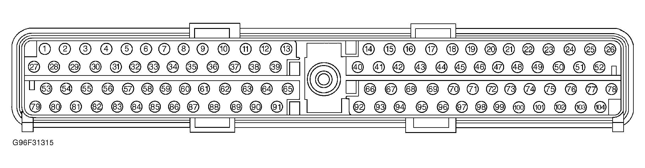 Courtesy of FORD MOTOR CO.