Test F: Seat Belt Warning Indicator & Chime Inoperative
- Turn ignition switch to LOCK position. Disconnect instrument cluster Black 12-pin harness connector C220b. Turn ignition switch to ON position. Measure voltage between ground and instrument cluster Black 12-pin harness connector C220b terminal No. 7 (Dark Green/Light Green wire). See Fig 1. If voltage is 10 volts or less, go to next step. If voltage is more than 10 volts, replace instrument cluster. See FUEL GAUGE SENDING UNIT under REMOVAL & INSTALLATION. Retest system operation.
- Turn ignition switch to LOCK position. Disconnect chime module Gray 7-pin harness connector C2156. Chime module is located behind center of instrument cluster. Measure resistance of Dark Green/Light Green wire between instrument cluster Black 12-pin harness connector C220b terminal No. 7 and chime module Gray 7-pin harness connector C2156 terminal No. 6. See Fig 1 and Fig 2
. If resistance is less than 5 ohms, replace chime module. Retest system operation. If resistance is 5 ohms or more, repair open in Dark Green/Light Green wire. See WIRING DIAGRAMS . Retest system operation.
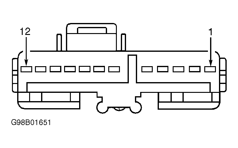 Courtesy of FORD MOTOR CO.
 Courtesy of FORD MOTOR CO.