Test M: High Beam Indicator Inoperative
- Turn ignition switch to LOCK position. Disconnect instrument cluster Black 12-pin harness connector C220b. Turn ignition switch to ON position. Turn headlight switch to high beams. Measure voltage between ground and instrument cluster Black 12-pin harness connector C220b terminal No. 9 (Light Green/Black wire). See Figure. If voltage is 10 volts or less, go to next step. If voltage is more than 10 volts, replace instrument cluster. See INSTRUMENT CLUSTER under REMOVAL & INSTALLATION. Retest system operation.
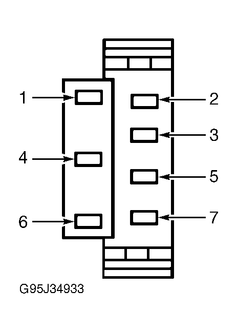
- Disconnect multifunction switch Gray 7-pin harness connector C202b. Measure resistance of Light Green/Black wire between instrument cluster Black 12-pin harness connector C220b terminal No. 9 and multifunction switch Gray 7-pin harness connector C202b terminal No. 5. See Figure and Fig 1
. If resistance is less than 5 ohms, repair headlight system as necessary. See EXTERIOR LIGHTS in SYSTEM WIRING DIAGRAMS article in ELECTRICAL. If resistance is more than 5 ohms, repair open in Light Green/Black wire. See WIRING DIAGRAMS . Retest system operation.
 Courtesy of FORD MOTOR CO.