Test L: Safety Belt Indicator Inoperative/Does Not Operate Properly (Chime Operates)
- Turn ignition switch to LOCK position. Connect New Generation Star (NGS) tester to Data Link Connector (DLC). DLC is located below driver's side of instrument panel, right of steering column. Turn ignition switch to RUN position. Monitor Generic Electronic Module (GEM) PIDs IGN_KEY, IGN_S, IGN_R and IGN_A while cycling ignition switch through all positions. If PIDs agree with ignition switch positions, go to next step. If PIDs do not agree with ignition switch positions, test ignition switch. See IGNITION SWITCH under COMPONENT TESTS in STEERING COLUMN SWITCHES - MUSTANG article.
- Using NGS tester, monitor GEM PID D_SBELT while buckling and unbuckling driver's seat belt. NGS tester should display IN with seat belt buckled and OUT with seat belt unbuckled. If PID agrees with seat belt position, go to next step. If PID does not agree with seat belt position, perform TEST Z: SEAT BELT WARNING CHIME DOES NOT OPERATE PROPERLY
.
- Turn ignition switch to LOCK position. Ensure seat belt is unbuckled. Turn ignition switch to RUN position while monitoring seat belt indicator. Seat belt indicator should illuminate for 3 seconds, then go out. If seat belt indicator operates as specified, go to step 10
. If seat belt indicator does not operate as specified, go to next step.
- Buckle driver's seat belt. If seat belt indicator is always illuminated, go to next step. If seat belt indicator is not always illuminated, go to step 7
.
- Turn ignition switch to LOCK position. Disconnect 26-pin Generic Electronic Module (GEM) harness connector C352. GEM is located behind left side of instrument panel, next to Central Junction Box (CJB). Turn ignition switch to RUN position. If seat belt indicator is always on, go to next step. If seat belt indicator goes out, go to step 10
.
- Turn ignition switch to LOCK position. Disconnect 12-pin instrument cluster harness connector C250. It may be necessary to remove instrument cluster for access to connector. See REMOVAL & INSTALLATION
. Measure resistance between ground and 26-pin GEM harness connector C352 terminal No. 26 (Dark Green/Light Green wire). See Fig 1
. If resistance is more than 10 k/ohms, go to step 11
. If resistance is 10 k/ohms or less, repair short to ground in Dark Green/Light Green wire between instrument cluster and GEM. See WIRING DIAGRAMS
.
- Turn ignition switch to LOCK position. Disconnect 12-pin instrument cluster harness connector C250. It may be necessary to remove instrument cluster for access to connector. See REMOVAL & INSTALLATION
. Disconnect 26-pin Generic Electronic Module (GEM) harness connector C352. GEM is located behind left side of instrument panel, next to Central Junction Box (CJB). Measure voltage between ground and GEM harness connector C352 terminal No. 26 (Dark Green/Light Green wire). See Fig 1
. If voltage does not exist, go to next step. If voltage exists, repair short to voltage in Dark Green/Light Green wire between instrument cluster and GEM. See WIRING DIAGRAMS
.
- Connect instrument cluster harness connector C250. Connect a fused jumper wire between ground and GEM harness connector C352 terminal No. 26 (Dark Green/Light Green wire). Turn ignition switch to RUN position. If seat belt indicator does not illuminate, go to next step. If seat belt indicator illuminates, go to step 10
.
- Turn ignition switch to LOCK position. Disconnect instrument cluster harness connector C250. Measure resistance in Dark Green/Light Green wire between GEM harness connector C352 terminal No. 26 and instrument cluster harness connector C250 terminal No. 4. See Fig 1
and Figure
. If resistance is 5 ohms or less, go to step 11
. If resistance is more than 5 ohms, repair open in Dark Green/Light Green wire between instrument cluster and GEM. See WIRING DIAGRAMS
.
- Disconnect all GEM harness connectors. Inspect all GEM harness connectors for loose, damaged or corroded terminals. If terminals are damaged, repair as necessary. If terminals are not damaged, reconnect all GEM harness connectors. Ensure GEM harness connectors are seated properly. If problem still exists, replace GEM. See REMOVAL & INSTALLATION
.
- Disconnect all instrument cluster harness connectors. Inspect all instrument cluster harness connectors for loose, damaged or corroded terminals. If terminals are damaged, repair as necessary. If terminals are not damaged, reconnect all instrument cluster harness connectors. Ensure instrument cluster harness connectors are seated properly. If problem still exists, replace instrument cluster module. See REMOVAL & INSTALLATION
.
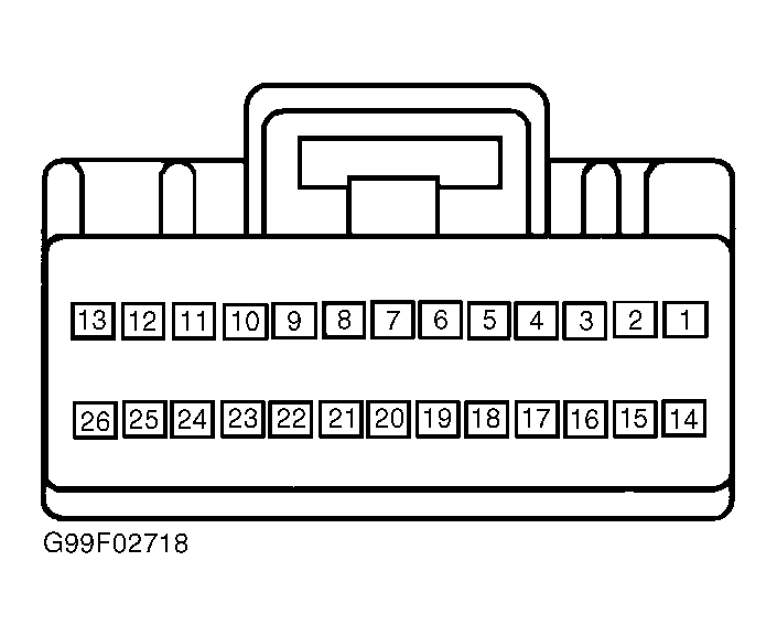 Courtesy of FORD MOTOR CO.