Test Z: Check Suspension Indicator Inoperative
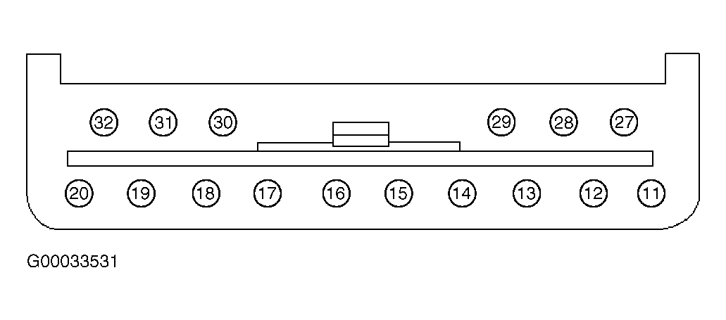
- Turn ignition switch to LOCK position. Disconnect air suspension control module Gray 16-pin harness connector C2000. Module is located behind left center of instrument panel. Connect a fused (7.5-amp) jumper wire between ground and air suspension control module Gray 16-pin harness connector terminal No. 12 (Dark Green/Light Green wire). See Fig 1
. Turn ignition switch to RUN position. If CHECK SUSP indicator is not illuminated, go to next step. If CHECK SUSP indicator is illuminated, repair air suspension concern. See appropriate ELECTRONIC article in SUSPENSION.
- Turn ignition switch to LOCK position. Remove instrument cluster. See INSTRUMENT CLUSTER
under REMOVAL & INSTALLATION. Measure resistance of Dark Green/Light Green wire between air suspension control module Gray 16-pin harness connector C2000 terminal No. 12 and instrument cluster White 10-pin harness connector C288 terminal No. 9. See Figure
and Fig 1
. If resistance is less than 5 ohms, go to next step. If resistance is 5 ohms or more, repair open in Dark Green/Light Green wire. Recheck system operation.
- Turn ignition switch to RUN position. Measure voltage between ground and instrument cluster White 16-pin harness connector C286 terminal No. 13 (Red/Yellow wire). See Figure
. If more than 10 volts exist, replace printed circuit. See PRINTED CIRCUIT
under REMOVAL & INSTALLATION. Recheck system operation. If 10 volts or less exist, repair open in Red/Yellow wire between Central Junction Box (CJB) and instrument cluster. Recheck system operation.
 Courtesy of FORD MOTOR CO.