Test A: No Scan Tool Communication With Generic Electronic Module
- Turn ignition switch to LOCK position. Disconnect Generic Electronic Module (GEM) 18-pin harness connector C240D located on Central Junction Box (CJB). CJB is located on lower left side of instrument panel, near kick panel. Measure voltage between ground and GEM 18-pin harness connector C240D terminals No. 4 (Red wire) and No. 16 (Black/Light Green wire). See Fig 1. If battery voltage is present, go to next step. If battery voltage is not present, replace CJB. Retest system operation.
- Disconnect GEM 26-pin harness connector C240A located on CJB. Measure resistance between ground and GEM 26-pin harness connector C240A terminal No. 26 (Pink/Orange wire). See Fig 2. If resistance is 5 ohms or less, test GEM. See MODULE COMMUNICATIONS NETWORK - EXCURSION & F250-F550 SUPER DUTY PICKUPS article. If resistance is more than 5 ohms, repair open in Pink/Orange wire between GEM and ground point. Ground point is located behind driver's kick panel. Retest system operation.
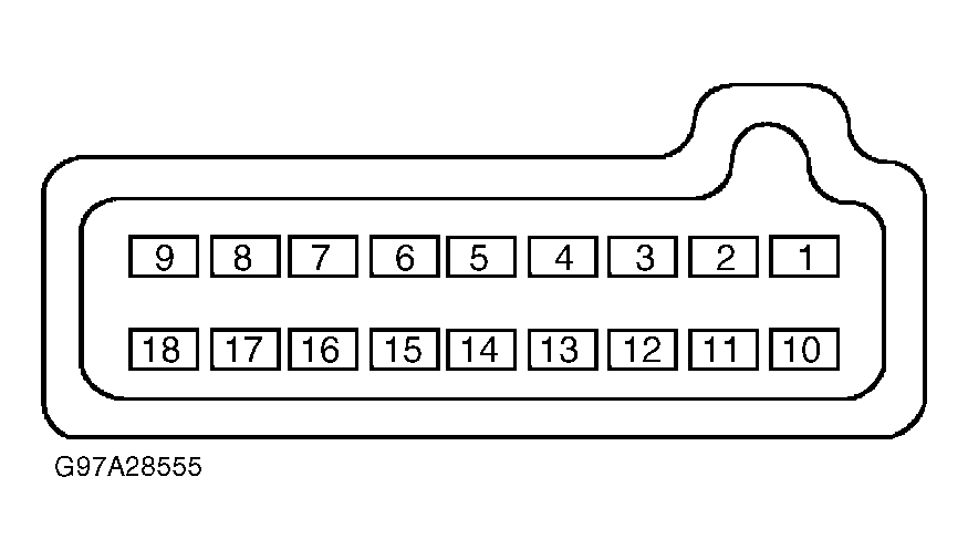 Courtesy of FORD MOTOR CO.
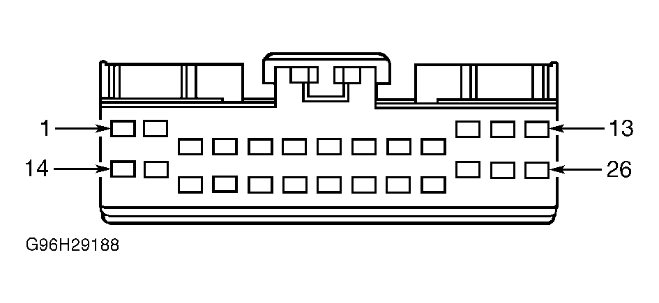 Courtesy of FORD MOTOR CO.