Test J: Speed Control Indicator Never On
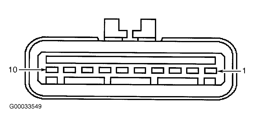
- Turn ignition switch to LOCK position. Disconnect speed control servo 10-pin harness connector C122. Speed control servo is located near right front side of engine compartment. Connect a 10-amp fused jumper wire between ground and speed control servo harness connector terminal No. 1 (Orange/Light Blue wire). See Fig 1
. Turn ignition switch to RUN position. If cruise indicator does not illuminate, go to next step. If cruise indicator illuminates, repair cruise control concern. See CRUISE CONTROL SYSTEMS - ESCAPE article.
- Disconnect instrument cluster 16-pin harness connector C220b. See Figure
. Measure resistance of Orange/Light Blue wire between instrument cluster harness connector C220b terminal No. 15 and speed control servo harness connector C122 terminal No. 1. See Figure
and Fig 1
. If resistance is less than 5 ohms, go to next step. If resistance is 5 ohms or more, repair open in Orange/Light Blue wire.
- Turn ignition switch to RUN position. Measure voltage between ground and instrument cluster harness connector C220b terminal No. 15 (Orange/Light Blue wire). See Figure
. If voltage does not exist, go to next step. If voltage exists, repair short to voltage in Orange/Light Blue wire.
- Disconnect all instrument cluster harness connectors. Inspect for corrosion or pushed out pins. Connect all instrument cluster harness connectors. Operate system and verify if concern still exists. If concern still exists, replace instrument cluster. If concern does not exist, system is operating correctly at this time. Concern may have been caused by a loose or corroded connector.
 Courtesy of FORD MOTOR CO.