Test D: Incorrect Fuel Gauge Indication (DTC B1202 & DTC B1204)
- Using New Generation Star (NGS) tester, perform instrument cluster self-test. If DTC B1202 or B1204 is not retrieved, go to next step. If DTC B1202 or B1204 is retrieved, go to step 6
.
- Using NGS tester, select FUEL LEVEL CONTROL active command. Trigger and monitor FUEL LEVEL to 0%, 50% and 100%. Fuel gauge should read E at 0%, half at 50% and F at 100%. If fuel gauge is as specified, go to next step. If fuel gauge is not as specified, go to step 6
.
- Turn ignition switch to LOCK position. Disconnect fuel pump module 4-pin harness connector. Fuel pump module is located in fuel tank. Connect one lead of Instrument Gauge System Tester between fuel pump module harness connector terminals No. 2 (Yellow/White wire) and No. 4 (Black/White wire). Set Instrument Gauge System Tester to 15 ohms. Turn ignition switch to RUN position and wait one minute. Fuel gauge should read empty or below. Turn ignition switch to LOCK position. Set Instrument Gauge System Tester to 160 ohms. Turn ignition switch to RUN position and wait one minute. Fuel gauge should read full or higher. If fuel gauge is as specified, go to next step. If fuel gauge is not as specified, replace fuel pump module.
- Visually inspect fuel tank for damage or deformation. If fuel tank is okay, go to next step. If fuel tank is not okay, replace fuel tank. Retest system operation.
- Inspect fuel pump module assembly for damaged wiring or connectors. Inspect float and float rod for damage or obstruction. If fuel pump module assembly is okay, replace fuel level sender. Retest system operation. If fuel pump module assembly is not okay, repair as necessary. Retest system operation.
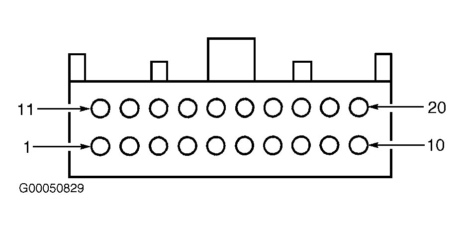
- Turn ignition switch to LOCK position. Disconnect instrument cluster 20-pin harness connector C220a. See Figure
. Disconnect fuel pump module 4-pin harness connector. Fuel pump module is located in fuel tank. Measure resistance of Yellow/White wire between instrument cluster harness connector C220a terminal No. 6 and fuel pump module harness connector terminal No. 2. See Fig 1
. Measure resistance between ground and instrument cluster harness connector C220a terminal No. 6 (Yellow/White wire). Resistance should be less than 5 ohms between instrument cluster and fuel pump module and 10 k/ohms or more between instrument cluster and ground. If resistance is as specified, go to next step. If resistance is not as specified, repair open or short to ground in Yellow/White wire. Retest system operation.
- Measure resistance between ground and fuel pump module harness connector terminal No. 4 (Black/White wire). If resistance is less than 5 ohms, go to next step. If resistance is 5 ohms or more, repair open in Black/White wire between fuel pump module and ground. Ground point is located behind left side of instrument panel. See Figure
.
- Turn ignition switch to RUN position. Measure voltage between ground and instrument cluster harness connector C220a terminal No. 6 (Yellow/White wire). See Fig 1
. If voltage does not exist, go to next step. If voltage exists, repair short to voltage in Yellow/White wire between instrument cluster and fuel pump module.
- Disconnect all instrument cluster harness connectors. Inspect for corrosion or pushed out pins. Connect all instrument cluster harness connectors. Operate system and verify if concern still exists. If concern still exists, replace instrument cluster. If concern does not exist, system is operating correctly at this time. Concern may have been caused by a loose or corroded connector.
 Courtesy of FORD MOTOR CO.