Test A: No Communication With Instrument Cluster
- Turn ignition switch to LOCK position. Disconnect instrument cluster 18-pin harness connector C220c. See Figure
for location. Turn ignition switch to RUN position. Measure voltage between ground and instrument cluster harness connector C220c terminals No. 2 (Red/Yellow wire), No. 3 (Black/Pink wire) and No. 4 (Orange/Light Green wire). See Fig 1
. If all voltages are 10 volts or more, go to next step. If any voltage is less than 10 volts, repair open in appropriate wire.
- Turn ignition switch to LOCK position. Measure resistance between ground and instrument cluster harness connector C220c terminals No. 1 (Black/White wire) and No. 18 (Black wire). If both resistances are less than 5 ohms, repair module communications concern. See MODULE COMMUNICATIONS NETWORK - ESCAPE article. If either resistance is 5 ohms or more, repair open in Black/White wire or Black wire.
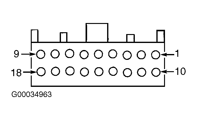 Courtesy of FORD MOTOR CO.