Test A: Instrument Cluster Display(S) Inoperative Or Erratic: Coupe
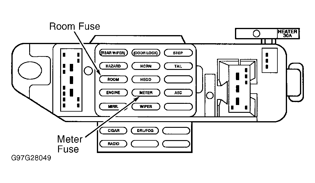
- Turn ignition off. Check METER fuse (10-amp). See Fig 1
. If fuse is okay, go to next step. If fuse is not blown, go to next step. If fuse is blown, replace 10-amp METER fuse. Turn ignition on and inspect fuse. If fuse fails again, check and repair short to ground as necessary. See WIRING DIAGRAMS
.
 Courtesy of FORD MOTOR CO.
- Turn ignition on. Measure voltage between ground and top terminal (right terminal) of METER fuse holder (Blue wire). If voltage is more than 10 volts, reinstall fuse and go to next step. If voltage is less than 10 volts, repair power feed for METER fuse. See WIRING DIAGRAMS
.
- Turn ignition off. Remove instrument cluster. See INSTRUMENT CLUSTER
under REMOVAL & INSTALLATION. Disconnect all instrument cluster harness connectors. Turn ignition on. Measure voltage between ground and instrument cluster harness connector C254 terminal No. 6 (Black/Yellow wire). See Figure
. Measure voltage between ground and instrument cluster harness connector C252 terminal No. 12 (Black/Yellow wire). See Figure
. Measure voltage between ground and instrument cluster harness connector C253 terminals No. 4 and 12 (Black/Yellow wire). See Figure
. Voltage should be more than 10 volts at each Black/Yellow wire. If voltage is more than 10 volts, go to next step. If voltage is less than 10 volts, repair Black/Yellow wire(s) in question. See WIRING DIAGRAMS
.
- Turn ignition off. Measure resistance between ground and instrument cluster harness connector C254 terminal No. 5 (Black/Green wire). Measure resistance between ground and instrument cluster harness connector C252 terminals No. 11 (Blue wire) and No. 8 (Black wire). Measure resistance between ground and instrument cluster harness connector C253 terminal No. 6 (Black/Green wire). Resistance should be less than 5 ohms. If resistance is less than 5 ohms on all wires, replace instrument cluster printed circuit and gauge contact clips. See PRINTED CIRCUIT
under REMOVAL & INSTALLATION. If any resistance is more than 5 ohms, repair circuit(s) in question. See WIRING DIAGRAMS
.