Test A: Shift Solenoid Electrical Circuit: Testing
- Electronic Diagnosis
Ensure transmission harness connector is in acceptable condition. Repair as necessary. Connect NGS tester to DLC. Perform KEY-ON-ENGINE-OFF (KOEO) SELF-TEST until continuous memory code(s) have been displayed. See QUICK TEST under DIAGNOSIS & TESTING. Select OUTPUT TEST MODE on NGS tester. Select ALL ON MODE and press START. If vehicle enters Output Test Mode (OTM), go to next step. If vehicle will not enter OTM, see SCAN TOOL UNABLE TO COMMUNICATE under DIAGNOSIS & TESTING.
- Check Electrical Signal Operation
Disconnect transmission 12-pin harness connector. Inspect condition of connector. Repair as needed. Using DVOM, connect positive lead to transmission harness connector VPWR terminal, and connect negative lead to suspect solenoid circuit. See Fig 1. Press START and STOP to cycle solenoid output on and off. Solenoid output voltage should change to about battery voltage while cycling outputs. If solenoid output voltage is as specified, go to step 5. If solenoid output voltage is not as specified, go to next step.
- Check Continuity Of Solenoid Signal & VPWR Circuits
Turn ignition switch to OFF position. Disconnect PCM 104-pin harness connector, and inspect it for damaged terminals, corrosion and loose wires. Repair as necessary. Install breakout box, leaving PCM disconnected. On Federal models equipped with 7.3L diesel engine, measure and record resistance between breakout box pins No. 1 and 27 and transmission harness connector terminals No. 2 (Violet/Orange wire) and 3 (Orange/Yellow wire). See Fig 1. On California models equipped with 7.3L diesel engine and all gasoline engines, measure and record resistance between breakout box pins No. 6 and 11 and transmission harness connector terminals No. 2 (Violet/Orange wire) and 3 (Orange/Yellow wire). On all models, measure and record resistance between breakout box VPWR pins No. 71 and 97 and transmission harness connector terminal No. 1 (Red/Yellow wire). If any resistance is greater than 5 ohms, repair open circuit. Connect all components. Disconnect breakout box. Repeat QUICK TEST under DIAGNOSIS & TESTING. If all resistances are 5 ohms or less, go to next step.
- Check Shift Solenoid Circuits For Shorts To Power & Ground
On Federal models equipped with 7.3L diesel engine, measure and record resistance between breakout box pins No. 1 and 27 and VPWR pins No. 71 and 97. On California models equipped with 7.3L diesel engine and all gasoline engines, measure and record resistance between breakout box pins No. 6 and 11 (PCM signal), and between breakout box pins No. 71 and 97 (VPWR control power). On Federal models equipped with 7.3L diesel engine, measure and record resistance between breakout box pins No. 1 and 27 and PCM signal pins No. 51, 76, 77, 91, 103 and ground. On California models equipped with 7.3L diesel engine and all gasoline engines, measure and record resistance between breakout box pins No. 6 and 11 and PCM signal pins No. 51, 76, 77, 91, 103 and ground. See Fig 1. If any resistance is less than 10 k/ohms, repair short in appropriate circuit. Connect all components. Disconnect breakout box. Repeat QUICK TEST under DIAGNOSIS & TESTING. If each resistance is 10 k/ohms or more, go to next step.
- Solenoid Functional Test
Connect transmission tester to transmission 12-pin harness connector. Perform solenoid voltage test. See tester manufacturer's instructions. If solenoid activates (LED Green), go to next step. If LED does not light (solenoid shorted to ground or open circuit), or indicates short to battery voltage (LED Red), go to step 7.
- Transmission Drive Test
Disconnect breakout box and reconnect PCM harness connector. Perform DYNAMIC TESTING - ENGINE ON test. See tester manufacturer's instructions. If solenoid output voltage changes to battery voltage, replace PCM. If solenoid output voltage does not change to battery voltage, go to next step.
- Check Resistance Of Solenoids
Place tester Bench/Drive switch to BENCH MODE. Place Gear Select switch in OHMS CHECK position. Connect ohmmeter negative lead to SS1 terminal and positive lead to VPWR terminal on tester. Record resistance. Connect ohmmeter negative lead to SS2 terminal and positive lead to VPWR terminal on tester. Resistance should be 20-30 ohms. If each resistance is within specification, go to next step. If any resistance is not within specification, replace solenoid body assembly. Erase all DTCs. See CLEARING DIAGNOSTIC TROUBLE CODES under DIAGNOSIS & TESTING. Repeat QUICK TEST .
- Check Solenoid For Short To Ground
Check continuity between BAT (-) tester terminal and SS1 and SS2 tester terminals. Check continuity between BAT (-) tester terminal and each VPWR terminal on tester. If continuity exists for any circuit, replace solenoid body assembly. Erase all DTCs. See CLEARING DIAGNOSTIC TROUBLE CODES under DIAGNOSIS & TESTING. Repeat QUICK TEST . If continuity does not exist, diagnose problem by symptom. See SYMPTOM DIAGNOSIS under TROUBLE SHOOTING.
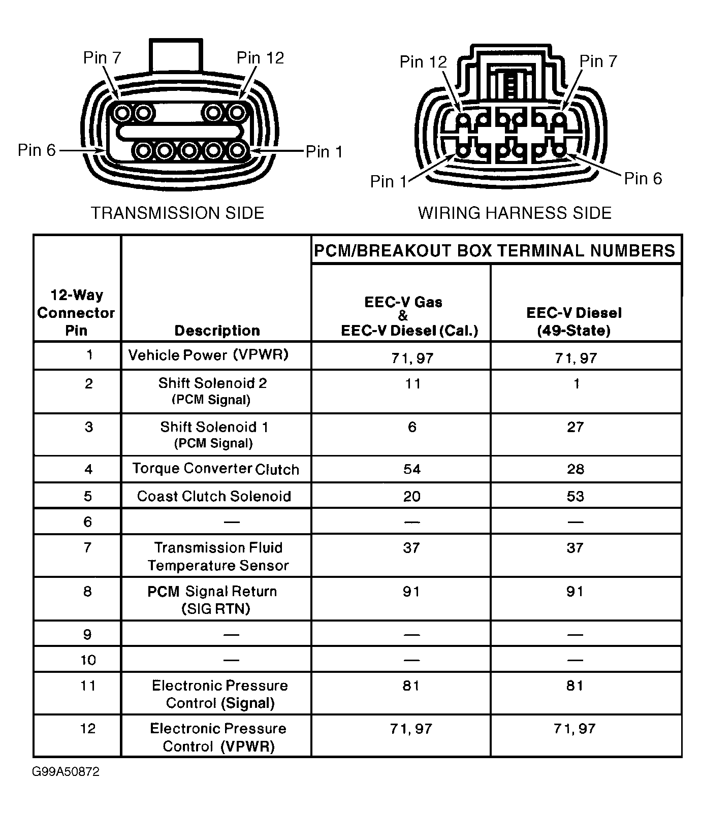 Courtesy of FORD MOTOR CO.