Test I: Tachometer Reads Incorrectly
- Turn ignition switch to LOCK position. Disconnect instrument cluster harness connectors C250b and C250a. Measure resistance between ground and terminal No. 8 (Black/White wire) at instrument cluster harness connector C250b. See Figure. Also measure resistance between ground and terminal No. 1 (Black/Yellow wire) instrument cluster connector C250a. See Figure. If each resistance is 5 ohms or less, go to next step. If resistance is more than 5 ohms, repair affected circuit and retest.
- Disconnect Powertrain Control Module (PCM) connector C1027. Measure resistance of White/Pink wire between terminal No. 12 at instrument cluster connector C250b and terminal No. 48 (terminal No. 19 on vehicles equipped with diesel engine) at PCM harness connector C1027. See Fig 1. If resistance is 5 ohms or less, go to next step. If resistance is more than 5 ohms, repair open in White/Pink wire.
- Measure resistance between ground and terminal No. 12 (White/Pink wire) at instrument cluster connector C250b. If resistance is more than 10 k/ohms, go to next step. If resistance is 10 k/ohms or less, repair short to ground in White/Pink wire.
- Check tachometer output signal. See appropriate SELF-DIAGNOSTICS article in ENGINE PERFORMANCE for test procedure. If tachometer output circuit is okay, replace instrument cluster. See INSTRUMENT CLUSTER under REMOVAL & INSTALLATION. If tachometer output circuit is faulty, appropriate SELF-DIAGNOSTICS article in ENGINE PERFORMANCE to continue diagnosis.
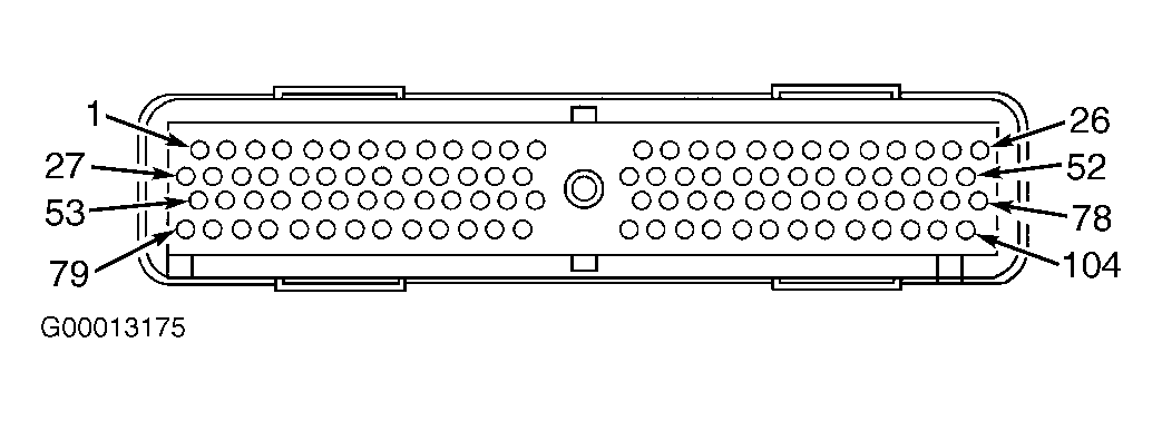 Courtesy of FORD MOTOR CO.