Ring & Pinion Gear Backlash
- With drive pinion depth and preload adjustments correct, remove pinion flange using holder and flange remover. Coat pinion oil seal with multipurpose grease. Install pinion oil seal.
- Ensure spring behind lip of seal remains in place during seal installation. If spring is dislodged, remove and replace seal. Install pinion flange and tighten pinion flange nut to specification. See TORQUE SPECIFICATIONS .
- Install differential case into axle housing. Differential master bearings should still be on case. Install outboard spacers. Set dial indicator so dial indicator tip is against back of ring gear, at 90 degrees to gear.
- Force ring gear away from drive pinion gear. With force still applied to ring gear, zero dial indicator. Force ring gear and case toward drive pinion gear to obtain a reading on indicator. Repeat this procedure until same reading is obtained each time.
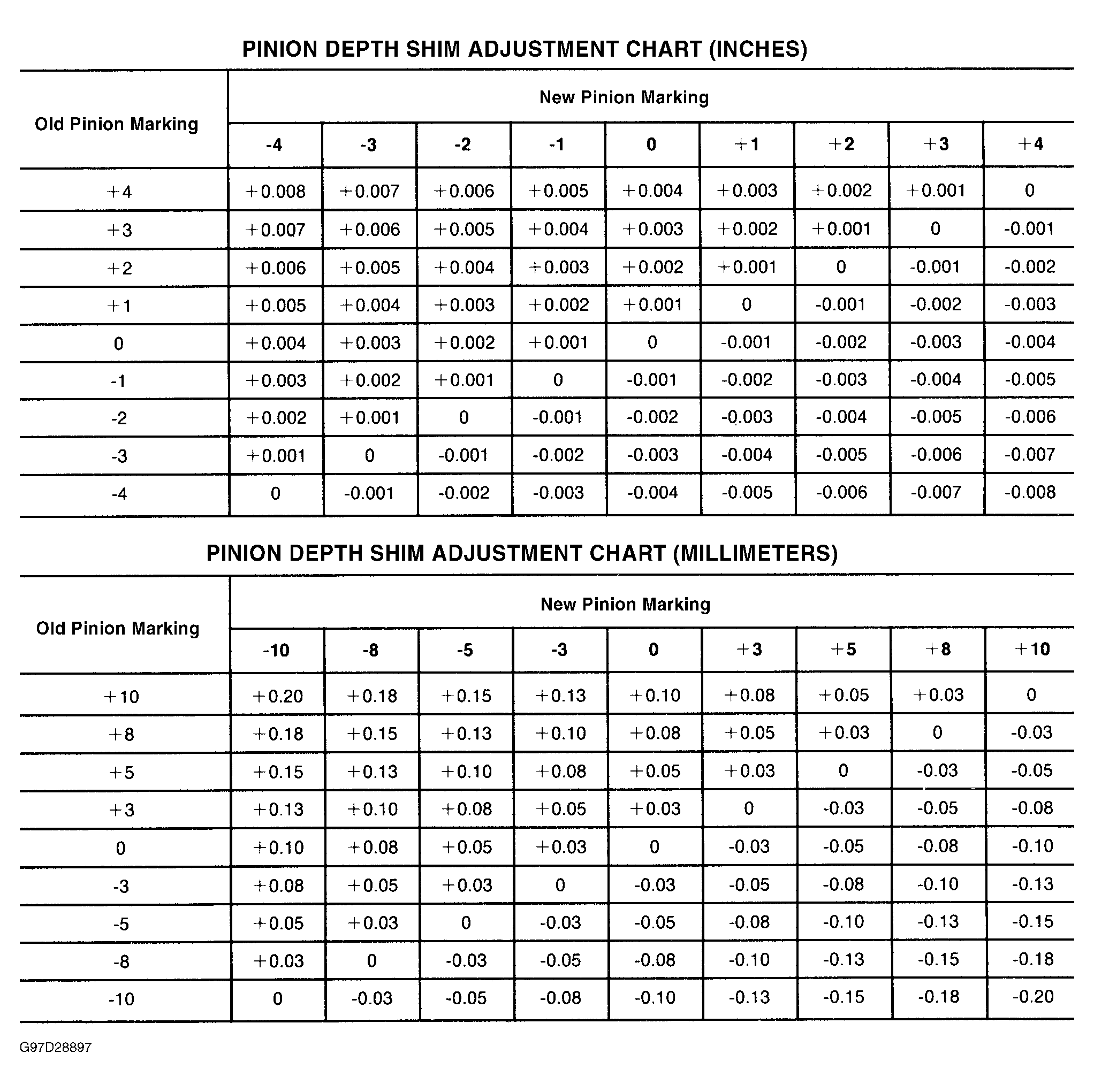
- The reading obtained is thickness of shim pack that must go under differential side bearing on ring gear side of case. Remove dial indicator. Remove differential case from housing. Remove master bearings from differential case. Place shim pack of correct thickness onto ring gear hub. See Figure.
- Drive side bearing onto case using Side Bearing Installer (205-D044). On Dana 50 and 60 axles, support case on opposite side with Step Plate (205-D018) while installing side bearing. On Dana 80 axle, use Step Plate (205-D019).
- On all applications, to determine correct amount of shims to placed onto pinion gear side hub, subtract thickness of shim pack installed on ring gear side of case from total differential case end play. Total differential case end play was recorded in step 6 in DIFFERENTIAL CASE procedure.
- On Dana 50 and 60 axles, add .015" (.38 mm) to figure for remaining end play. On Dana 80 axle, add .010" (.25 mm) to figure. On all applications, result is thickness of shim pack to be installed onto hub of differential case opposite ring gear (drive pinion side of case).
- Place shim pack on case hub and drive side bearing onto case using side bearing installer. Support case with step plate to protect side bearing already installed onto ring gear side of case.
- Install housing spreader and dial indicator onto axle housing. Set tip of dial indicator at same point used when case was removed from housing during disassembly procedure. Spread housing to a maximum of .015" (.38 mm). Damage could occur if housing is spread further. Remove dial indicator.
- Place side bearing outer races onto side bearings. Install differential case into axle housing. Use soft-face hammer to seat case assembly into axle housing bore. DO NOT damage teeth of drive pinion and ring gears. Remove spreader from housing.
- Install side bearing caps, ensuring letters stamped on caps match letters stamped on housing. Tighten cap bolts to specification. See TORQUE SPECIFICATIONS . Check ring and pinion gear backlash in 3 places equally spaced around ring gear. Backlash range is .005-.008" (.13-.20 mm), with an allowable maximum variation of .002" (.05 mm).
- If backlash figure is high, move ring gear closer to drive pinion gear. If backlash figure is low, move ring gear away from drive pinion gear. To change backlash readings, move shims from one side of differential case to the other.
- Using an INCH-lb. torque wrench, measure drive pinion total preload. With new bearings installed, reading should be 6 to 9 INCH lbs. (.7 to 1.0 N.m) higher than initial reading taken under DRIVE PINION BEARING PRELOAD procedure. Initial reading was taken without differential case installed in axle housing.
- If total preload reading is high, remove an equal amount of shims from each differential case hub. If total preload reading is low, add an equal amount of shims to each differential case hub.
- Verify final pinion position using gear tooth contact pattern. See GEAR TOOTH CONTACT PATTERNS article in GENERAL INFORMATION. Pattern should be correct if assembly and adjustments have been done properly.
- When backlash is correct, install axle shafts. See AXLE SHAFT under REMOVAL & INSTALLATION. Install NEW gasket (if applicable) and housing cover. Tighten cover bolts to specification. See TORQUE SPECIFICATIONS . Fill assembly with hypoid lubricant.
 Courtesy of FORD MOTOR CO.