Test A: No Communication With Generic Electronic Module
- Turn ignition off. Remove Generic Electronic Module (GEM). See GENERIC ELECTRONIC MODULE under REMOVAL & INSTALLATION. Measure voltage between junction box/fuse relay panel 18-pin connector C240d terminals No. 4 and 16 and ground. See Fig 1. If both voltage values are greater than 10 volts, go to next step. If either voltage value is not greater than 10 volts, replace junction box/fuse relay panel.
- Ensure ignition is off. Disconnect GEM 26-pin connector C240a. Measure resistance between GEM 26-pin harness connector C240a terminal No. 26 (Pink/Orange wire) and ground. See Fig 2. If resistance is less than 5 ohms, repair module communication concern. See MODULE COMMUNICATIONS NETWORK -- EXCURSION & F250-F550 SUPER DUTY PICKUPS
article. If resistance is not less than 5 ohms, repair open circuit in Pink/Orange wire. Retest system for normal operation.
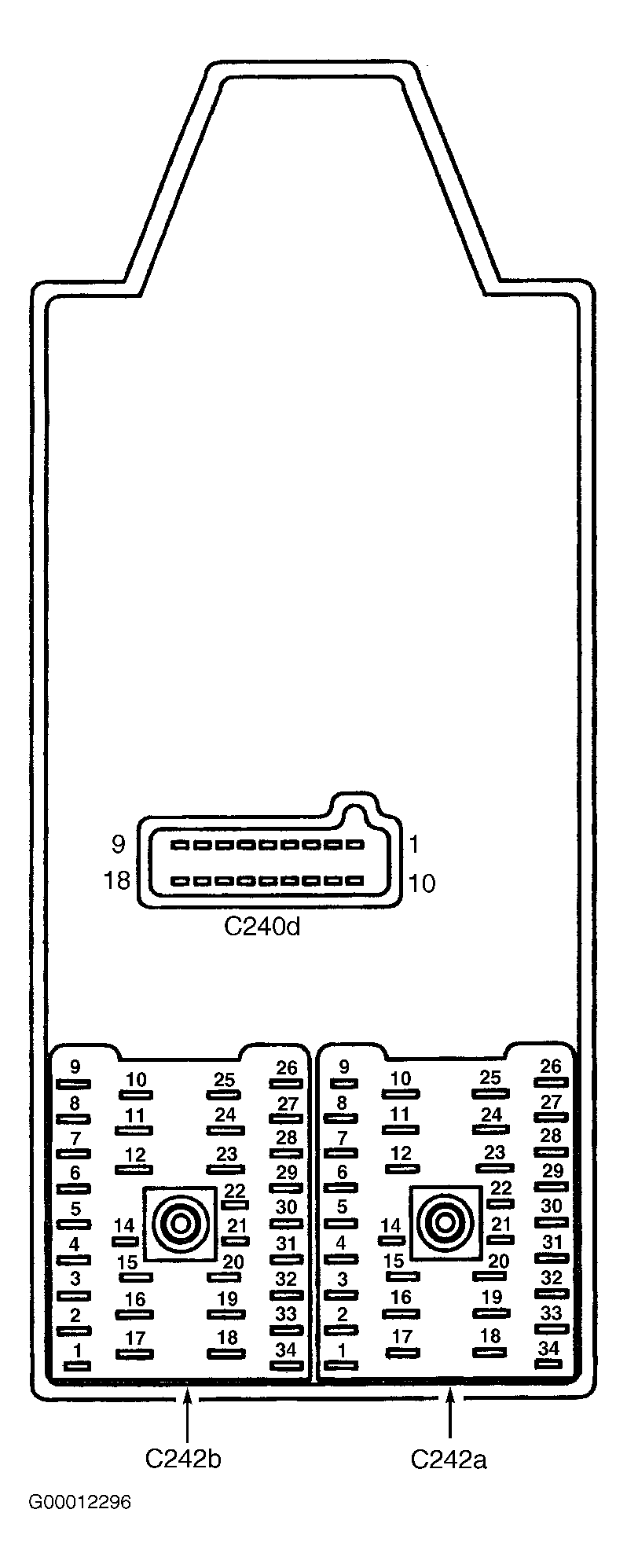 Courtesy of FORD MOTOR CO.
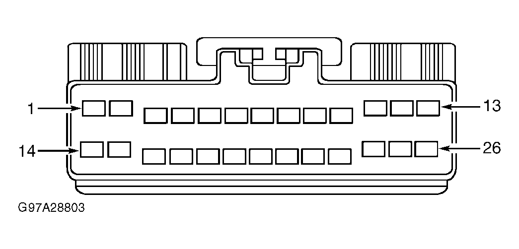 Courtesy of FORD MOTOR CO.