Test B: All Gauges Inoperative
- Turn ignition switch to RUN position. Observe instrument cluster warning indicator lights. Turn ignition switch to START position. If SERVICE ENGINE SOON, battery, seat belt, brake and anti-lock brake system lights prove out, go to step 3. If all lights do not prove out, go to next step.
- Turn ignition switch to LOCK position. On Excursion, check CJB fuses No. 2 (5-amp), No. 19 (10-amp) and No. 29 (5-amp). On Super Duty, check CJB fuses No. 15 (5-amp), No. 19 (10-amp) and No. 29 (5-amp). If all fuses are okay, go to next step. If any fuse is blown, replace fuse. Test system operation. If fuse blows again, repair short to ground in appropriate wire. See appropriate POWER DISTRIBUTION article in WIRING DIAGRAMS.
- Verify instrument cluster connectors are connected correctly. Partial removal of instrument cluster is necessary. See INSTRUMENT CLUSTER under REMOVAL & INSTALLATION. Verify instrument cluster connector between instrument cluster printed circuit and instrument cluster is connected properly. If all connectors are connected properly, go to next step. If any connectors are not connected properly, reconnect and retest.
- Disconnect instrument cluster connectors C250a and C250b. Turn ignition switch to RUN position. Measure resistance between ground and terminals No. 12 (Red/Yellow wire) and No. 7 (White/Yellow wire) at instrument cluster harness connector C250a. See Fig 1. Measure resistance between ground and terminal No. 3 (Red/White wire on Excursion; Light Blue/Black wire, Super Duty) and terminal No. 11 (Red/Yellow wire) at instrument cluster harness connector C250b. See Fig 2. If battery voltage is present, go to next step. If battery voltage not present, repair open in appropriate wire and retest.
- Measure resistance between ground and terminal No. 5 (Pink/Orange wire) at instrument cluster harness connector C250b. If resistance is 5 ohms or less, and instrument cluster printed circuit connector is fully seated, replace instrument cluster. See INSTRUMENT CLUSTER under REMOVAL & INSTALLATION. If resistance is more than 5 ohms, repair open in Pink/Orange wire and retest.
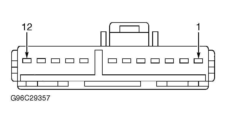 Courtesy of FORD MOTOR CO.
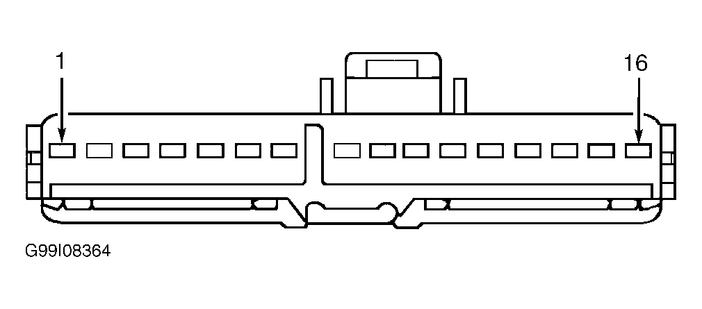 Courtesy of FORD MOTOR CO.