Climate Control System: Notes
WARNING: This page is about a different car, the 2005 Ford Pickup, 2005 Ford F550 Super Duty, 2005 Ford F450 Super Duty, and 2005 Ford Cab & Chassis. However, it is still accessible from the selected car via links, so may be relevant.
Refer to SYSTEM WIRING DIAGRAM
for schematic and connector information.
SPECIAL TOOLS
|
|
Worldwide Diagnostic System (WDS) Vehicle Communication Module (VCM) with appropriate adapters, or equivalent diagnostic tool |
|
|
R-134a Manifold Gauge Set 176-R032A or equivalent |
|
|
Connector, Refrigerant Pressure Line 412-093 (T94P-19623-E) |
|
|
Set, A/C Fittings 412-DS028 (D93L-19703-B) or equivalent |
|
|
Refrigerant Leak Detector 216-00001 or equivalent |
|
|
Pressure Tester 014-R1072 or equivalent |
|
|
Fluke 77 III Automotive Meter 105-R0056 or equivalent |
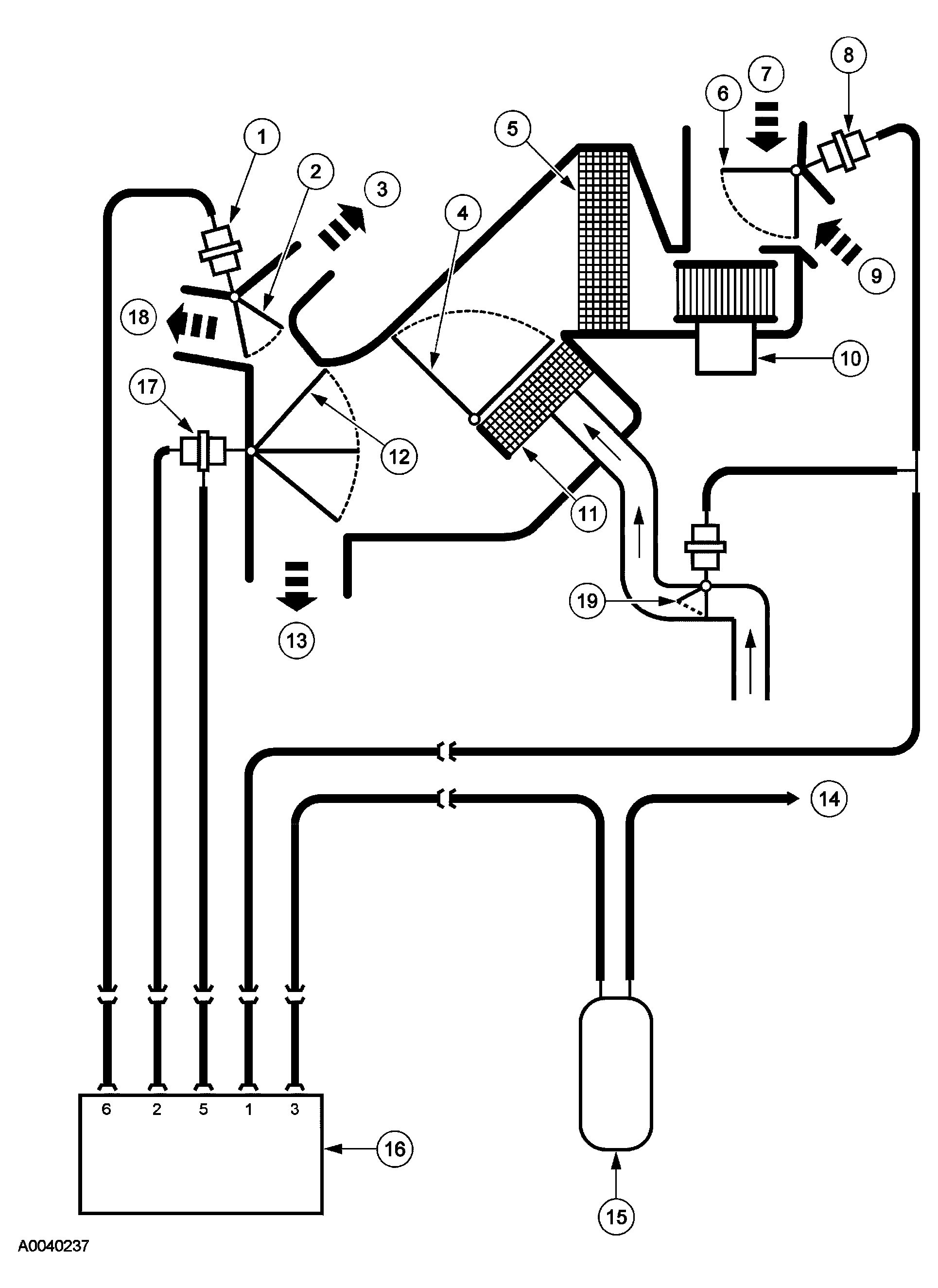 Courtesy of FORD MOTOR CO.
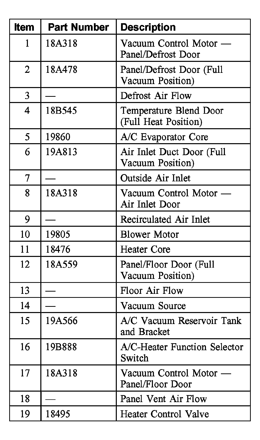 Courtesy of FORD MOTOR CO.
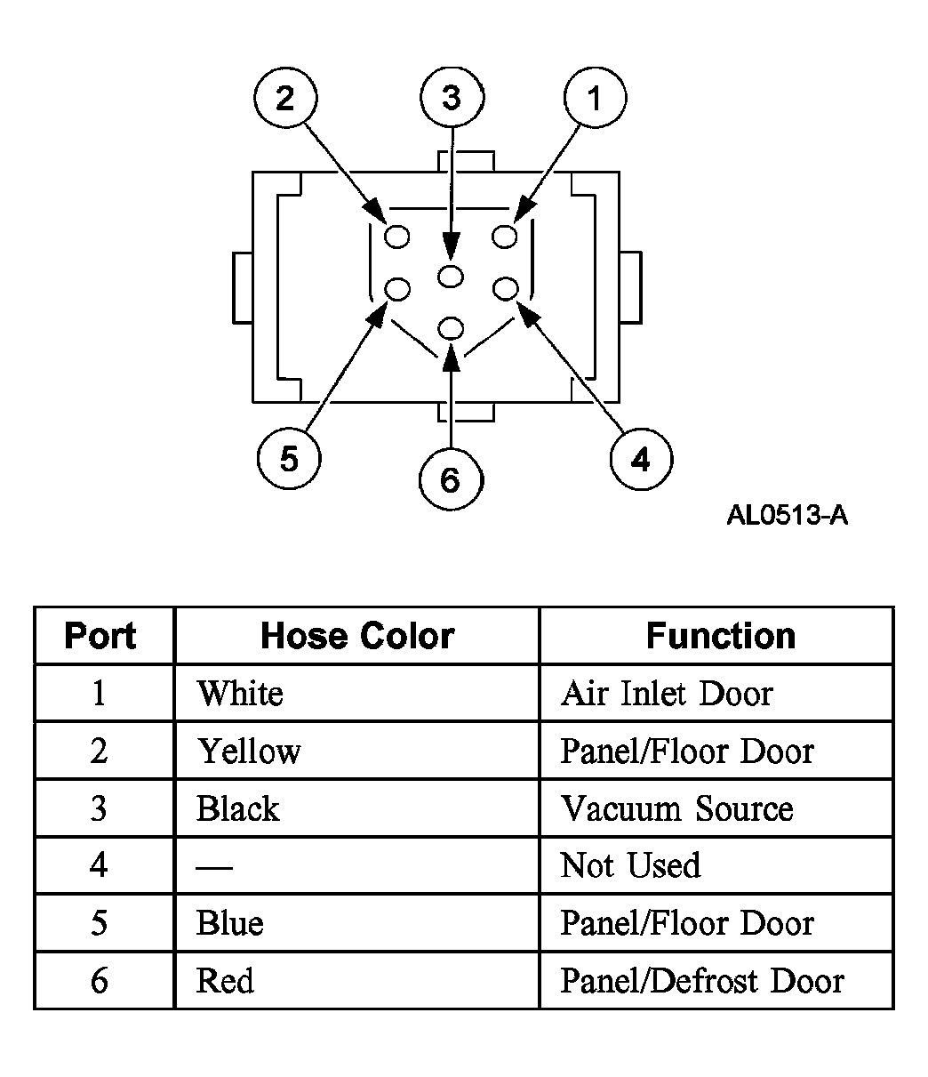 Courtesy of FORD MOTOR CO.
 VACUUM APPLICATION CHART - MANUAL A/C
| Switch Port |
Color |
Function |
Function Selector Switch Position |
| MAX A/C |
A/C |
PANEL |
OFF |
PNL/ FLR |
FLOOR |
FLR/ DEF |
DEF |
| 1 |
White |
Retire/ Fresh and Heater Control Valve |
V |
NV |
NV |
V |
NV |
NV |
NV |
NV |
| 2 |
Yellow |
Panel/ Floor |
NV |
NV |
NV |
V |
NV |
V |
NV |
NV |
| 3 |
Black |
Vacuum Source |
V |
V |
V |
V |
V |
V |
V |
V |
| 5 |
Blue |
Panel/ Floor |
NV |
NV |
NV |
V |
V |
V |
V |
NV |
| 6 |
Red |
Panel/ Defrost |
V |
V |
V |
NV |
V |
NV |
NV |
NV |
V = Vacuum
NV= No Vacuum |
 Courtesy of FORD MOTOR CO.
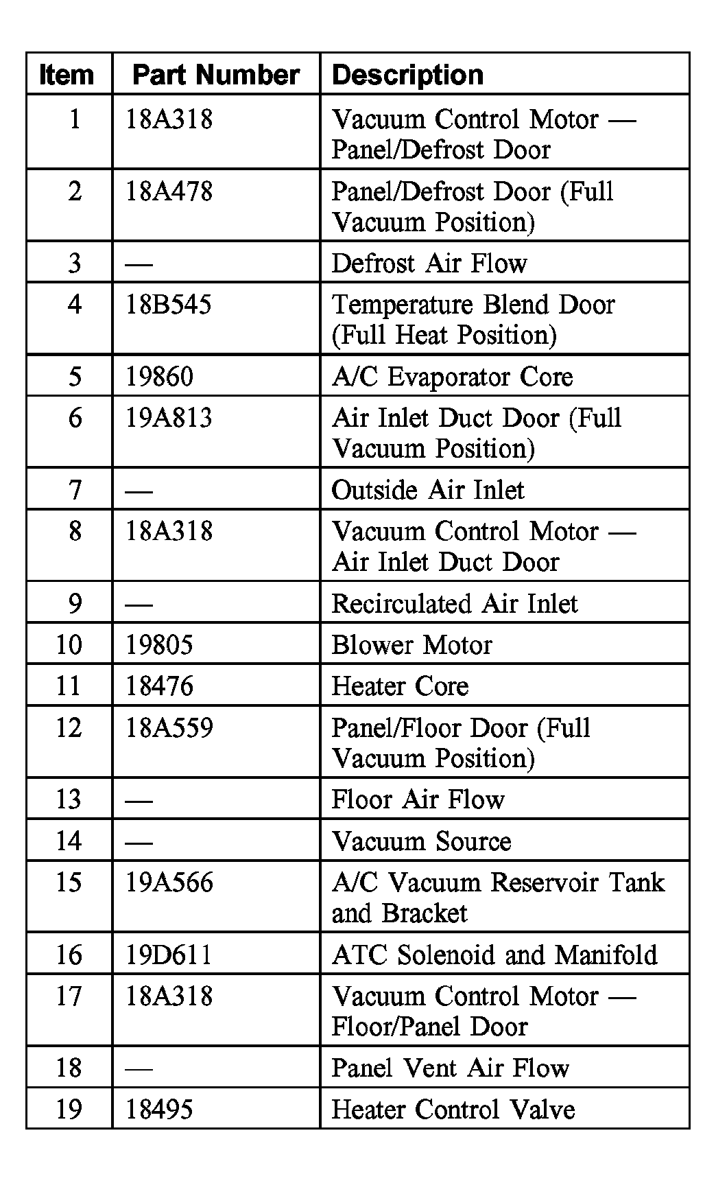 Courtesy of FORD MOTOR CO.
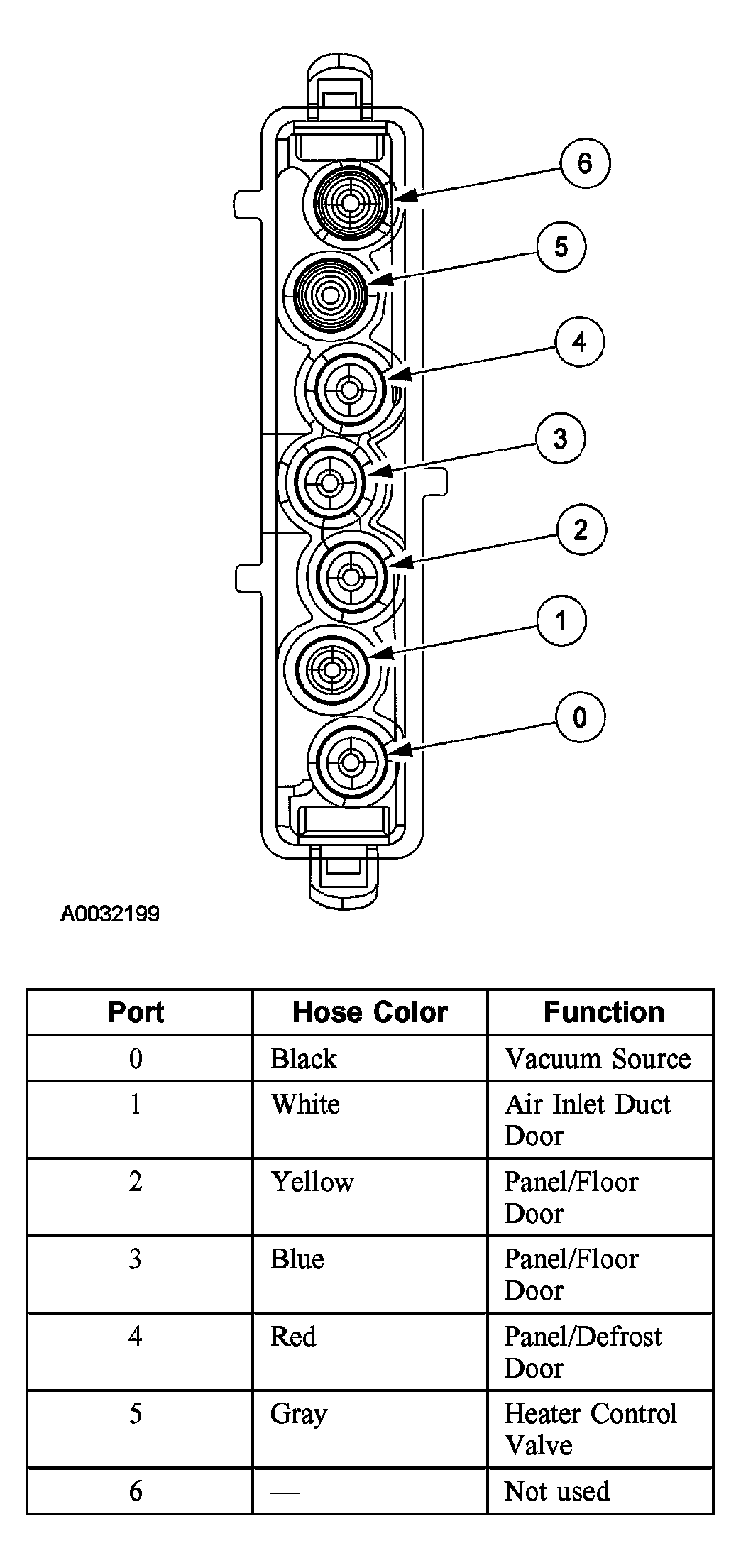 Courtesy of FORD MOTOR CO.
 VACUUM APPLICATION CHART - EATC
| Port |
Color |
Function |
Manual Override Buttons |
| OFF |
PANEL |
PNL/FLR |
FLR |
FLR/DEF |
DEF |
| 0 |
Black |
Vacuum Source |
V |
V |
V |
V |
V |
V |
| 1 |
White |
Air Inlet |
V |
V/NV |
V/NV |
V/NV |
V/NV |
NV |
| 2 |
Yellow |
Panel/Floor |
V |
NV |
NV |
V |
NV |
NV |
| 3 |
Blue |
Panel/Floor |
V |
NV |
V |
V |
V |
NV |
| 4 |
Red |
Panel/ Defrost |
NV |
V |
V |
NV |
NV |
NV |
| 5 |
Gray |
Heater Control Valve |
V |
V/NV |
V/NV |
V/NV |
V/NV |
V/NV |