Electronic Throttle Control System Strategy
WARNING: This page does not describe the selected car, but rather 30 other vehicles, including the 2004 Mercury Sable, 2004 Mercury Mountaineer, 2004 Mercury Monterey, 2004 Mercury Marauder, and 2004 Mercury Grand Marquis. However, it is still accessible from the selected car via links, so may be relevant.
As stated earlier the torque based ETC strategy was developed mainly to improve fuel economy and to accommodate Variable Cam Timing. This is possible by not coupling the throttle angle to the drivers pedal position. By uncoupling the throttle angle (produce engine torque) from pedal position (driver demand). This allows the powertrain control strategy to optimize fuel control and transmission shift schedules while delivering the requested wheel torque. ETC is used on the 2004 MY Lincoln LS and Ford Thunderbird, Explorer/Mountaineer, and the new light-duty F-series.
The ETC monitor system is distributed across two processors within the PCM: the main powertrain control processor unit (CPU) and a monitoring processor called an Enhanced-Quizzer (E-Quizzer) processor. The primary monitoring function is performed by the Independent Plausibility Check (IPC) software, which resides on the main processor. It is responsible for determining the driver-demanded torque and comparing it to an estimate of the actual torque delivered. If the generated torque exceeds driver demand by specified amount, the IPC takes appropriate mitigating action.
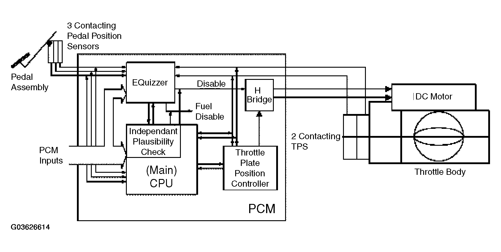 Courtesy of FORD MOTOR CO.
Since the IPC and main controller share the same processor, they are subject to a number of potential, common failure modes. Therefore, the E-Quizzer processor was added to redundantly monitor selected PCM inputs and to act as an intelligent watchdog and monitor the performance of the IPC and the main processor. If it determines that the IPC function is impaired in any way, it takes appropriate Failure Mode and Effects Management (FMEM) actions.
ETC SYSTEM FAILURE MODE AND EFFECTS MANAGEMENT:
| Effect |
Failure Mode |
| No Effect on Driveability |
A loss of redundancy or loss of a non-critical input could result in a fault that does not affect driveability. The ETC light will turn on, but the throttle control and torque control systems will function normally. |
| Disable Speed Control |
If certain failures are detected, speed control will be disabled. Throttle control and torque control will continue to function normally. |
| RPM Guard w/Pedal Follower |
In this mode, torque control is disabled due to the loss of a critical sensor or PCM fault. The throttle is controlled in pedal-follower mode as a function of the pedal position sensor input only. A maximum allowed RPM is determined based on pedal position (RPM Guard.) If the actual RPM exceeds this limit, spark and fuel are used to bring the RPM below the limit. The ETC light and the MIL are turned on in this mode and a P2106 is set. EGR, VCT, and IMRC outputs are set to default values. |
| RPM Guard w/ Default Throttle |
In this mode, the throttle plate control is disabled due to the loss of Throttle Position, the Throttle Plate Position Controller, or other major Electronic Throttle Body fault. A default command is sent to the TPPC, or the H-bridge is disabled. Depending on the fault detected, the throttle plate is controlled or springs to the default (limp home) position. A maximum allowed RPM is determined based on pedal position (RPM Guard.) If the actual RPM exceeds this limit, spark and fuel are used to bring the RPM below the limit. The ETC light and the MIL are turned on in this mode and a P2110 is set. EGR, VCT, and IMRC outputs are set to default values. |
| RPM Guard w/ High Forced Idle |
This mode is caused by the loss of 2 or 3 pedal position sensor inputs due to sensor, wiring, or PCM faults. The system is unable to determine driver demand, and the throttle is controlled to a fixed high idle airflow. There is no response to the driver input. The maximum allowed RPM is a fixed value (RPM Guard). If the actual RPM exceeds this limit, spark and fuel are used to bring the RPM below the limit. The ETC light and the MIL are turned on in this mode and a P2104 is set. EGR, VCT, and IMRC outputs are set to default values. Shutdown If a significant processor fault is detected, the monitor will force vehicle shutdown by disabling all fuel injectors. The ETC light and the MIL are turned on in this mode and a P2105 is set. |
| Shutdown |
If a significant processor fault is detected, the monitor will force vehicle shutdown by disabling all fuel injectors. The ETC light and the MIL are turned on in this mode and a P2105 is set. |
ELECTRONIC THROTTLE MONITOR OPERATION:
| DTCs |
|
| P0606 |
PCM processor failure (MIL, ETC light) |
| P2106 |
ETC FMEM - forced limited power; sensor fault: MAF, one TP, CKP, TSS, OSS, stuck throttle, throttle actuator circuit fault (MIL, ETC light) |
| P2110 |
ETC FMEM - forced limited rpm; two TPs failed; TPPC detected fault (MIL, ETC light) |
| P2104 |
ETC FMEM - forced idle, two or three pedal sensors failed (MIL, ETC light) |
| P2105 |
ETC FMEM - forced engine shutdown; EQuizzer detected fault (MIL, ETC light) |
| U0300 |
ETC software version mismatch, IPC, EQuizzer or TPPC (non-MIL, ETC light) |