Transmission Connector Layouts
WARNING: This page is about a different car, the 2007 Lincoln Mark LT and 2007 Ford Pickup. However, it is still accessible from the selected car via links, so may be relevant.
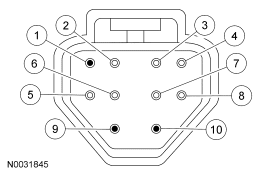 Courtesy of FORD MOTOR CO.
| Pin Number |
Circuit Function |
| 1 |
NOT USED |
| 2 |
Signal Return |
| 3 |
Torque Converter Clutch (TCC) Solenoid |
| 4 |
Vehicle Power |
| 5 |
Transmission Fluid Temperature (TFT) Input |
| 6 |
Electronic Pressure Control (EPC) Solenoid |
| 7 |
SSA |
| 8 |
SSB |
| 9 |
NOT USED |
| 10 |
NOT USED |
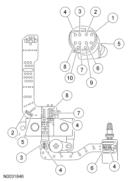 Courtesy of FORD MOTOR CO.
| Pin Number |
Circuit Function |
| 1 |
NOT USED |
| 2 |
Signal Return Transmission Fluid Temperature (TFT) |
| 3 |
Torque Converter Clutch (TCC) |
| 4 |
Vehicle Power To Solenoid |
| 5 |
Transmission Fluid Temperature (TFT) |
| 6 |
Electronic Pressure Control (EPC) |
| 7 |
SSA |
| 8 |
SSB |
| 9 |
NOT USED |
| 10 |
NOT USED |
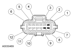 Courtesy of FORD MOTOR CO.
| Pin Number |
Circuit Function |
| 1 |
NOT USED |
| 2 |
Signal Return |
| 3 |
TR3A |
| 4 |
TR1 |
| 5 |
TR2 |
| 6 |
TR4 |
| 7 |
NOT USED |
| 8 |
NOT USED |
| 9 |
Fused Power Feed |
| 10 |
Starter Control |
| 11 |
Reverse |
| 12 |
Starter to Starter Interrupt Relay |
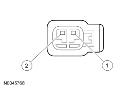 Courtesy of FORD MOTOR CO.
| Pin Number |
Circuit Function |
| 1 |
Signal Return |
| 2 |
Output Shaft Speed (OSS) Sensor |
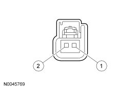 Courtesy of FORD MOTOR CO.
| Pin Number |
Circuit Function |
| 1 |
Turbine Shaft Speed (TSS) Sensor |
| 2 |
Signal Return |
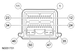 Courtesy of FORD MOTOR CO.
 DIGITAL TRANSMISSION RANGE (TR) SENSOR DIAGNOSIS CHART
| Selector Position |
PID: TR |
PID: TR_D |
PID: TR_V (volts) |
| TR4 |
TR3A |
TR2 |
TR1 |
TR3A |
| Park |
P/N |
0 |
0 |
0 |
0 |
0.0 Volt |
| In Between |
REV |
0 |
1 |
0 |
0 |
1.3-1.8 Volts |
| Reverse |
REV |
1 |
1 |
0 |
0 |
1.3-1.8 Volts |
| In Between |
REV |
0 |
1 |
0 |
0 |
1.3-1.8 Volts |
| Neutral |
NTRL |
0 |
1 |
1 |
0 |
1.3-1.8 Volts |
| In Between |
O/Da |
1 |
1 |
1 |
0 |
1.3-1.8 Volts |
| Overdrive |
O/Da |
1 |
1 |
1 |
1 |
1.3-1.8 Volts |
| In Between |
Man 2 |
1 |
0 |
1 |
1 |
0.0 Volt |
| Manual 2 |
Man 2 |
1 |
0 |
0 |
1 |
0.0 Volt |
| In Between |
Man 2 |
1 |
0 |
1 |
1 |
0.0 Volt |
| Manual 1 |
Man 1 |
0 |
0 |
1 |
1 |
0.0 Volt |
- TR_V is the voltage at the PCM pin 19 (TR3A circuit) to signal return.
- "In Between" reading could be caused by a selector lever cable or digital TR sensor misaligned or a digital TR sensor circuit failure of TR1, TR2, TR3A or TR4.
- TR_D: 1= Open Digital TR switch, 0= Closed Digital TR switch.
- Readings taken from PCM signal pins for TR1, TR2, TR3A, TR4 to signal return.
- Voltages for TR1, TR2, TR4:
- 0 = 0.0 volt.
- 1 = 9.0-14.0 volts.
- Voltage for TR3A:
- 0 = 0.0 volt.
- 1 = 1.3-1.8 volts.
Wiggle Test Information For Open/Shorts
- TR4, TR3A, TR2 and TR1 are all closed in PARK. PARK is a good position to check for intermittent open circuits (with scan tool monitoring TR_D).
- TR4, TR3A, TR2 and TR1 are all open in OVERDRIVE, so OVERDRIVE is a good position to check for shorts to ground. To determine the shorted components while observing TR_D, unplug the TR and see if the short goes away. If the short is still present, unplug the transmission harness and see if the short goes away. If the short is still present, then the short is in the PCM or vehicle harness. Remove the suspect circuit(s) wire from the PCM vehicle harness. If the short is still present, then the PCM has an internal failure. Otherwise the failure is in the vehicle harness.
|
| Pin Number |
Circuit Function |
| 14 |
Output Shaft Speed (OSS) Sensor |
| 15 |
Turbine Shaft Speed (TSS) Sensor |
| 17 |
Transmission Range (TR) Sensor TR1 |
| 18 |
TR Sensor TR2 |
| 19 |
TR Sensor TR3A |
| 20 |
Transmission Fluid Temperature (TFT) Sensor |
| 32 |
TR Sensor TR4 |
| 36 |
Torque Converter Clutch (TCC) |
| 37 |
Shift Solenoid 2 (SSB) |
| 38 |
Shift Solenoid 1 (SSA) |
| 39 |
Electronic Pressure Control (EPC) Solenoid |
| 43 |
Signal Return |
a
Will read "Drive" if O/D is canceled.