Test C: All Power Door Locks Operate From One Switch Only
- Turn ignition off. Disconnect inoperative door lock switch harness connector. Measure voltage between ground and inoperative door lock switch harness connector terminal No. 2. See Fig 1
. If more than 10 volts exists and vehicle is not equipped with anti-theft system, go to next step. If more than 10 volts and vehicle is equipped with anti-theft system, go to step 4
. On all models, if 10 volts or less exists, repair open in appropriate power circuit for power door lock switch. See WIRING DIAGRAMS
. Retest system operation.
- Remove power door lock control relay located in right side "A" pillar. Measure resistance between inoperative door lock switch harness connector terminal No. 7 and power door lock control relay harness connector C1911 terminal No. 5. See Figure
and Fig 1
. If resistance is less than 5 ohms, go to next step. If resistance is 5 ohms or more, repair open in appropriate circuit. See WIRING DIAGRAMS
. Retest system operation.
- Measure resistance between inoperative door lock switch harness connector terminal No. 1 and power door lock control relay harness connector C1911 terminal No. 5. See Figure
and Fig 1
. If resistance is less than 5 ohms, replace inoperative door lock switch and retest system operation. See DOOR LOCK SWITCH
under REMOVAL & INSTALLATION. If resistance is 5 ohms or more, repair open in appropriate circuit. See WIRING DIAGRAMS
. Retest system operation.
- Disconnect central locking module 13-pin harness connector C451B located in right side "A" pillar. Measure resistance between inoperative door lock switch harness connector terminal No. 7 and central locking module harness connector C451B terminal No. 3. See Figure
and Fig 1
. If resistance is less than 5 ohms, go to next step. If resistance is 5 ohms or more, repair open in appropriate circuit. See WIRING DIAGRAMS
. Retest system operation.
- Measure resistance circuit between inoperative door lock switch harness connector terminal No. 1 and central locking module harness connector C451B terminal No. 10. See Figure
and Fig 1
. If resistance is less than 5 ohms, replace inoperative door lock switch and retest system operation. See DOOR LOCK SWITCH
under REMOVAL & INSTALLATION. If resistance is 5 ohms or more, repair open in appropriate circuit. See WIRING DIAGRAMS
. Retest system operation.
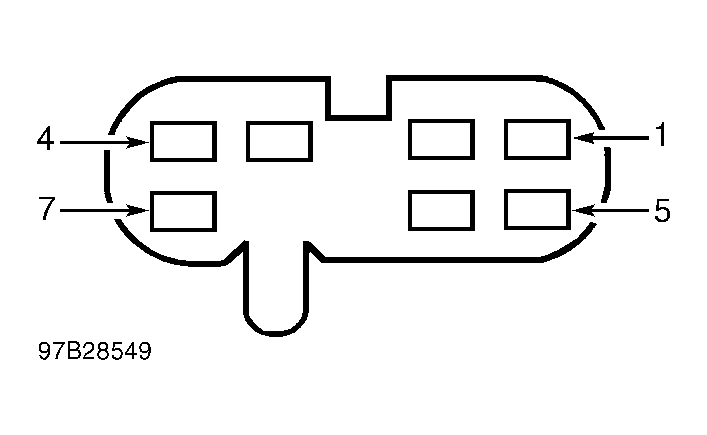 Courtesy of FORD MOTOR CO.