Test Z: Incorrect Fuel Gauge Indication In Gasoline Mode (Bi-Fuel Vehicles Only)
- Ensure vehicle is in gasoline mode. Turn ignition switch to LOCK position. Disconnect fuel pump intercept harness connector C4420, between fuel pump and fuel pump driver module. Disconnect fuel tank unit harness connector C732. Connect fuel pump intercept harness connector C4420 to fuel tank unit. Turn ignition switch to RUN position. If fuel gauge functions correctly, go to next step. If fuel gauge does not function correctly, replace fuel tank unit.
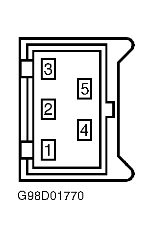
- Turn ignition to LOCK position. Disconnect compuvalve module harness connector C4025. Measure resistance between terminal No. 42 (White wire) at compuvalve harness connector C4025 and terminal No. 5 (White/Red wire) at fuel tank unit harness connector C732. See Fig 1
and Fig 2
. Resistance should be 5 ohms or less. Measure resistance between ground and terminal No. 42 (White wire) at compuvalve harness connector C4025. Resistance should be greater than 10 k/ohms. If resistance is as specified, go to next step. If resistance is not as specified, repair open or short in White, Dark Blue or White/Red wire.
- Turn ignition to RUN position. Measure voltage between ground and terminal No. 42 (White wire) at compuvalve harness connector C4025. If voltage exists, repair short to voltage in White, Dark Blue or White/Red wire. If battery voltage does not exist, replace compuvalve module. See REMOVAL, OVERHAUL & INSTALLATION - CNG/LPG (BI-FUEL)
article in ENGINE PERFORMANCE.
 Courtesy of FORD MOTOR CO.
 Courtesy of FORD MOTOR CO.