Test S: Turn Indicator Inoperative
- Turn ignition switch in RUN position. Place multifunction switch in left turn position. If left turn indicator does not illuminate, go to next step. If left turn indicator illuminates, go to step 5
.
- If left outside turn signals operate, go to next step. If left outside turn signals do not operate, locate and repair problem in exterior lighting system. See EXTERIOR LIGHTS article.
- Turn ignition switch to LOCK position. Disconnect instrument cluster harness connector C808A. Disconnect central junction box harness connector C362. See Figure
. Measure resistance of Blue/Black wire between terminal No. 3 at central junction box harness connector C362 and terminal No. 2 at instrument cluster harness connector C808A. See Figure
. If resistance is 5 ohms or less, go to next step. If resistance is more than 5 ohms, repair open in Blue/Black wire.
- Disconnect central timer module from back of central junction box. See Figure
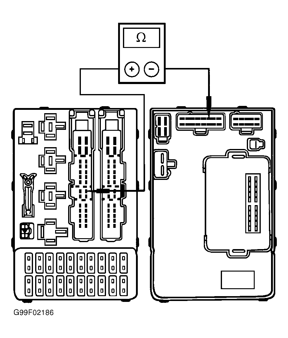
. Measure resistance between terminal No. 14 at central timer module harness connector (fuse box side) and terminal No. 3 at central junction box harness connector C362 (fuse box side). See Fig 1
. If resistance is 5 ohms or less, inspect left turn signal indicator bulb and replace as necessary. If bulb is okay, replace instrument cluster printed circuit. If resistance is more than 5 ohms, repair or replace central junction box as necessary.
- Turn ignition switch to RUN position. Place multifunction switch in right turn position. If right turn indicator does not illuminate, go to next step. If right turn indicator illuminates, system is okay at this time.
- If right outside turn signals operate, go to next step. If right outside turn signals do not operate, locate and repair problem in exterior lighting system. See EXTERIOR LIGHTS article.
- Turn ignition switch to LOCK position. Disconnect instrument cluster harness connector C808A. Disconnect central junction box harness connector C362. See Figure
. Measure resistance of Blue/Yellow wire between terminal No. 4 at central junction box harness connector C362 and terminal No. 3 at instrument cluster harness connector C808A. See Figure
. If resistance is 5 ohms or less, go to next step. If resistance is more than 5 ohms, repair open in Blue/Yellow wire.
- Disconnect central timer module from back of instrument panel. See Figure
. Measure resistance between terminal No. 16 at central timer module harness connector (fuse box side) at terminal No. 4 at central junction box harness connector C362 (fuse box side). See Fig 2
. If resistance is 5 ohms or less, inspect right turn signal indicator bulb and replace as necessary. If bulb is okay, replace instrument cluster printed circuit. If resistance is more than 5 ohms, repair or replace central junction box as necessary.
 Courtesy of FORD MOTOR CO.
 Courtesy of FORD MOTOR CO.