Test Q: High Beam Indicator Never/Always On
- Turn ignition switch to RUN position. Turn headlights on. Place multifunction switch to high beam position. If high beams operate properly, go to next step. If high beams do not operate properly, repair headlights as necessary. See appropriate wiring diagram in
HEADLIGHT SYSTEMS article.
- Turn headlights off. Turn ignition switch to LOCK position. Disconnect instrument cluster harness connector C250. Turn ignition switch to RUN position. Measure voltage at terminal No. 2 (Gray/White wire) at instrument cluster harness connector C250. See Figure
. If voltage is 5 volts or less, go to step 4
. If voltage is greater than 5 volts and vehicle is equipped with daytime running lights, go to next step. If voltage is greater than 5 volts and vehicle is not equipped with daytime running lights, repair short to voltage in Gray/White wire.
- Turn ignition switch to LOCK position. Disconnect Daytime Running Lights (DRL) module harness connector C186. Turn ignition switch to RUN position. Measure voltage at terminal No. 2 (Gray/White wire) at instrument cluster harness connector C250. If voltage is greater than 5 volts, repair short to voltage in Gray/White wire. If voltage is 5 volts or less, replace DRL module.
- Turn ignition switch to LOCK position. Disconnect instrument panel fuse box harness connector C235. Measure resistance in Gray/White wire between terminal No. 35 at instrument panel fuse box harness connector C235 and terminal No. 2 at instrument cluster harness connector C250. See Figure
and Fig 1
. If resistance is less than 3 ohms, go to next step. If resistance is 3 ohms or more, repair open in Gray/White wire.
- Disconnect both high beam headlight harness connectors. Measure resistance between ground and terminal No. 2 (Gary/White wire) at instrument cluster harness connector C250. If resistance is 10 k/ohms or less, repair short to ground in Gray/White wire. If resistance is greater than 10 k/ohms, go to next step.
- Check for continuity between high beam indicator bulb terminal (component side). If continuity exists, replace instrument cluster printed circuit. If continuity does not exist, replace bulb.
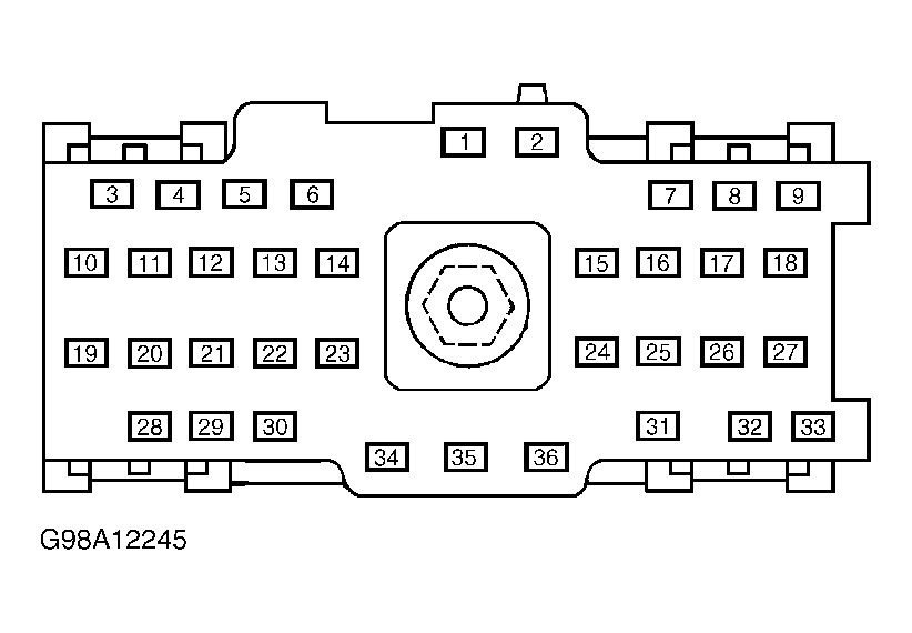 Courtesy of FORD MOTOR CO.