Test D: Fuel Gauge Inaccurate (Flex Fuel Vehicle)
- Turn ignition switch to LOCK position. Disconnect fuel pump/fuel gauge sender harness connector C496. Connect Instrument Gauge System Tester (014-R1063) to Yellow/White wire terminal at fuel pump/fuel gauge sender harness connector C496. Set tester to 11 ohms. Turn ignition switch to RUN position, wait 60 seconds. Fuel gauge should read empty or below. Turn ignition switch to LOCK position. Set tester to 115 ohms. Turn ignition switch to RUN position, wait 60 seconds. Fuel gauge should read full or above. If fuel does not respond as specified, disconnect tester and go to next step. If fuel gauge responds as specified, go to step 7
.
- Disconnect Flex Fuel Sensor Module (FFSM) harness connector C2040. Measure resistance in Black/Yellow wire between fuel pump/fuel gauge sender harness connector C496 and terminal No. 3 at FFSM harness connector C2040. See Fig 1
. If resistance is 5 ohms or less, go to next step. If resistance is greater than 5 ohms, repair open in Black/Yellow wire.
- Measure resistance in Yellow/White wire between fuel pump/fuel gauge sender harness connector C496 and terminal No. 4 at FFSM harness connector C2040. Resistance should be 5 ohms or less. Also, measure resistance between ground and terminal No. 3 (Yellow/White wire) at FFSM harness connector C2040. Resistance should be greater than 10 k/ohms. If both resistance readings are as specified, go to next step. If either resistance reading is not as specified, repair open and/or short to ground in Yellow/White wire.
- Connect Instrument Gauge System Tester (014-R1063) to terminal No. 6 (Orange/Light Green wire) at FFSM harness connector C2040. Set tester to 22 ohms. Turn ignition switch to RUN position, wait 60 seconds. Fuel gauge should read empty or below. Turn ignition switch to LOCK position. Set tester to 145 ohms. Turn ignition switch to RUN position, wait 60 seconds. Fuel gauge should read full or above. If fuel does not respond as specified, disconnect tester and go to next step. If fuel gauge responds as specified, replace FFSM.
- Turn ignition switch to LOCK position. Disconnect instrument cluster harness connector C250. Measure resistance in Orange/Light Green wire between terminal No. 7 at instrument cluster harness connector C250 and terminal No. 6 at FFSM harness connector C2040. See Figure
and Fig 1
. Resistance should be 5 ohms or less. Also, measure resistance between ground and terminal No. 6 (Orange/Light Green wire) at FFSM harness connector C2040. Resistance should be greater than 10 k/ohms. If both resistance readings are as specified, go to next step. If either resistance reading is not as specified, repair open and/or short to ground in Orange/Light Green wire.
- Measure resistance in Brown wire between terminal No. 8 at instrument cluster harness connector C250 and terminal No. 2 at FFSM harness connector C2040. If resistance is 5 ohms or less, replace fuel gauge. If resistance is greater than 5 ohms, repair open in Brown wire.
- Inspect fuel tank for damage. If fuel tank is okay, go to next step. If fuel tank is damaged, repair or replace fuel tank as necessary.
- Inspect fuel pump/fuel gauge sender assembly. Inspect fuel pump/fuel gauge sender wiring. If problem exists, repair or replace as necessary. If problem does not exist, replace fuel level sender.
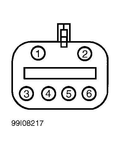 Courtesy of FORD MOTOR CO.