DTC B1323: Door Ajar Indicator Circuit Failure
- Close all doors. Turn ignition switch to RUN position. If door ajar indicator is on at all times, go to next step. If door ajar indicator is not on at all times, go to step 4
.
- Turn ignition switch to LOCK position. Disconnect Generic Electronic Module (GEM) harness connector C236. Measure resistance between ground and terminal No. 2 (Black/Orange wire) at GEM harness connector C236. See Fig 1
. If resistance is 10 k/ohms or less, go to next step. If resistance is greater than 10 k/ohms, replace GEM.
- Turn ignition switch to LOCK position. Disconnect instrument cluster harness connector C250. Measure resistance between ground and terminal No. 14 (Black/Orange wire) at instrument cluster harness connector C250. See Fig 2
. If resistance is 10 k/ohms or less, repair short to ground in Black/Orange wire. If resistance is greater than 10 k/ohms, replace instrument cluster printed circuit.
- Turn ignition switch to LOCK position. Disconnect instrument cluster harness connector C250. Disconnect Generic Electronic Module (GEM) harness connector C236. Measure resistance in Black/Orange wire between terminal No. 14 at instrument cluster harness connector C250 and terminal No. 2 at GEM harness connector C236. See Fig 1
and Fig 2
. If resistance is 5 ohms or less, go to next step. If resistance is greater than 5 ohms, repair open in Black/Orange wire.
- Remove door ajar bulb from instrument cluster. Measure resistance of bulb. If resistance is greater than 5 ohms, replace bulb. If resistance is 5 ohms or less, replace instrument cluster printed circuit.
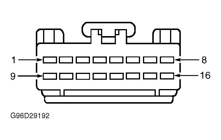 Courtesy of FORD MOTOR CO.
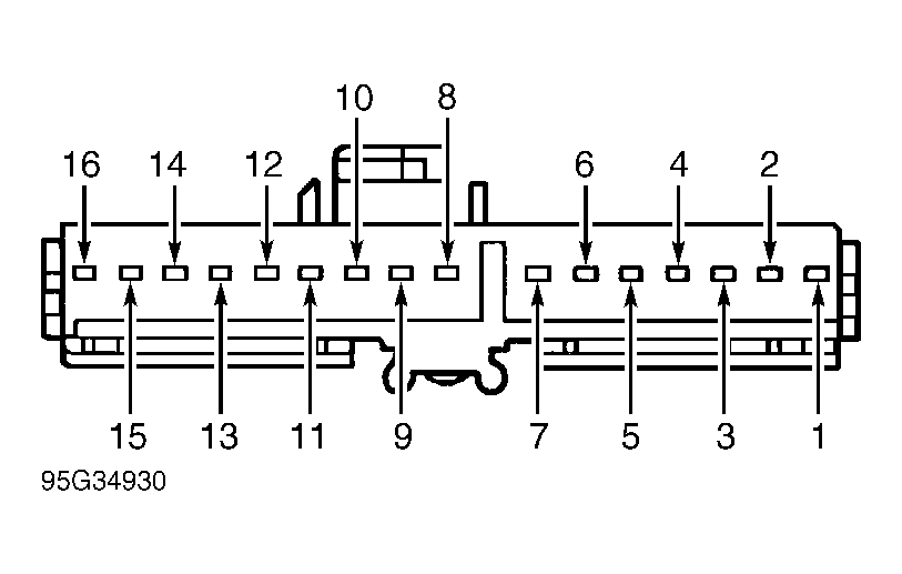 Courtesy of FORD MOTOR CO.