Test A: No Communication With Generic Electronic Module
- Remove fuse No. 23 from instrument panel fuse box. Measure resistance between ground and output side of fuse No. 23 in instrument panel fuse box. Resistance should start at greater than one m/ohm and drop steadily to less than 3 k/ohms. If resistance is not as specified, go to next step. If resistance is as specified, go to step 7
.
- If resistance in step 1
read greater than 10 ohms, go to next step. If resistance in step 1
read 10 ohms or less, go to step 4
.
- Remove Generic Electronic Module (GEM) from instrument panel fuse box. Disconnect and reconnect ohmmeter as in step 1
. If resistance is not greater than one m/ohm (may drop steadily to less than 3 k/ohms), go to next step. If resistance is greater than one m/ohm (may drop steadily to less than 3 k/ohms), replace GEM.
- Disconnect instrument panel fuse box harness connector C247. Measure resistance between ground and output side of fuse No. 23. If resistance is 10 k/ohms or less, replace instrument panel fuse box. If resistance is greater than 10 k/ohms and equipped with anti-theft system, connect instrument panel fuse box harness connector C247 and go to next step. If resistance is greater than 10 k/ohms and not equipped with anti-theft system, connect instrument panel fuse box harness connector C247 and go to step 7
.
- Disconnect Passive Anti-Theft System (PATS) module harness connector C242. Disconnect and reconnect ohmmeter as in step 1
. If resistance does not read greater than one m/ohm and drops steadily to less than 3 k/ohms, go to next step. If resistance reads greater than one m/ohm and drops steadily to less than 3 k/ohms, replace PATS module.
- Disconnect Remote Anti-Theft Personality (RAP) module harness connector C254. Disconnect and reconnect ohmmeter as in step 1
. If resistance reads greater than one m/ohm, replace RAP module. If resistance reads one m/ohm or less, repair short to ground in White/Yellow wire between fuse No. 23 and RAP module.
- Disconnect Generic Electronic Module (GEM) harness connector C248. Measure resistance between ground and terminals No. 14 and 25 (both Black wires) at GEM harness connector C248. See Fig 1
. If both resistance readings are 5 ohms or less, go to next step. If either resistance reading is greater than 5 ohms, repair open in appropriate wire(s).
- Disconnect GEM harness connector C223. Measure resistance between ground and terminal No. 12 (Black/White wire) at GEM harness connector C223. See Figure
. If resistance is 5 ohms or less, go to next step. If resistance is greater than 5 ohms, repair open in Black/White wire.
- Disconnect GEM harness connector C236. Turn ignition switch to RUN position. Measure voltage at terminal No. 14 (Red/Yellow wire) at GEM harness connector C236. See Figure
. If battery voltage does not exist, go to next step. If battery voltage exists, go to step 11
.
- Remove fuse No. 12 (5-amp) from instrument panel fuse box. Inspect fuse. If fuse tests okay, repair open in Red/Yellow wire between instrument panel fuse box and GEM. If fuse is blown, repair short to ground in Red/Yellow wire between instrument panel fuse box and GEM.
- Measure resistance between ground and terminal No. 22 (Black/Light Green wire) at GEM harness connector C223. If resistance is 5 ohms or less, repair module communication concern. See
MODULE COMMUNICATIONS NETWORK - SABLE & TAURUS article. If resistance is greater than 5 ohms, repair open in Black/Light Green wire.
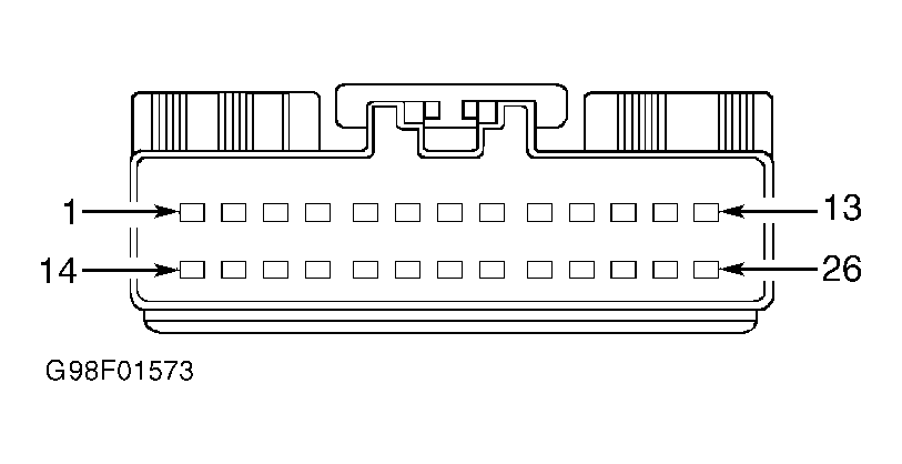 Courtesy of FORD MOTOR CO.