No Communication With Generic Electronic Module (Gem)
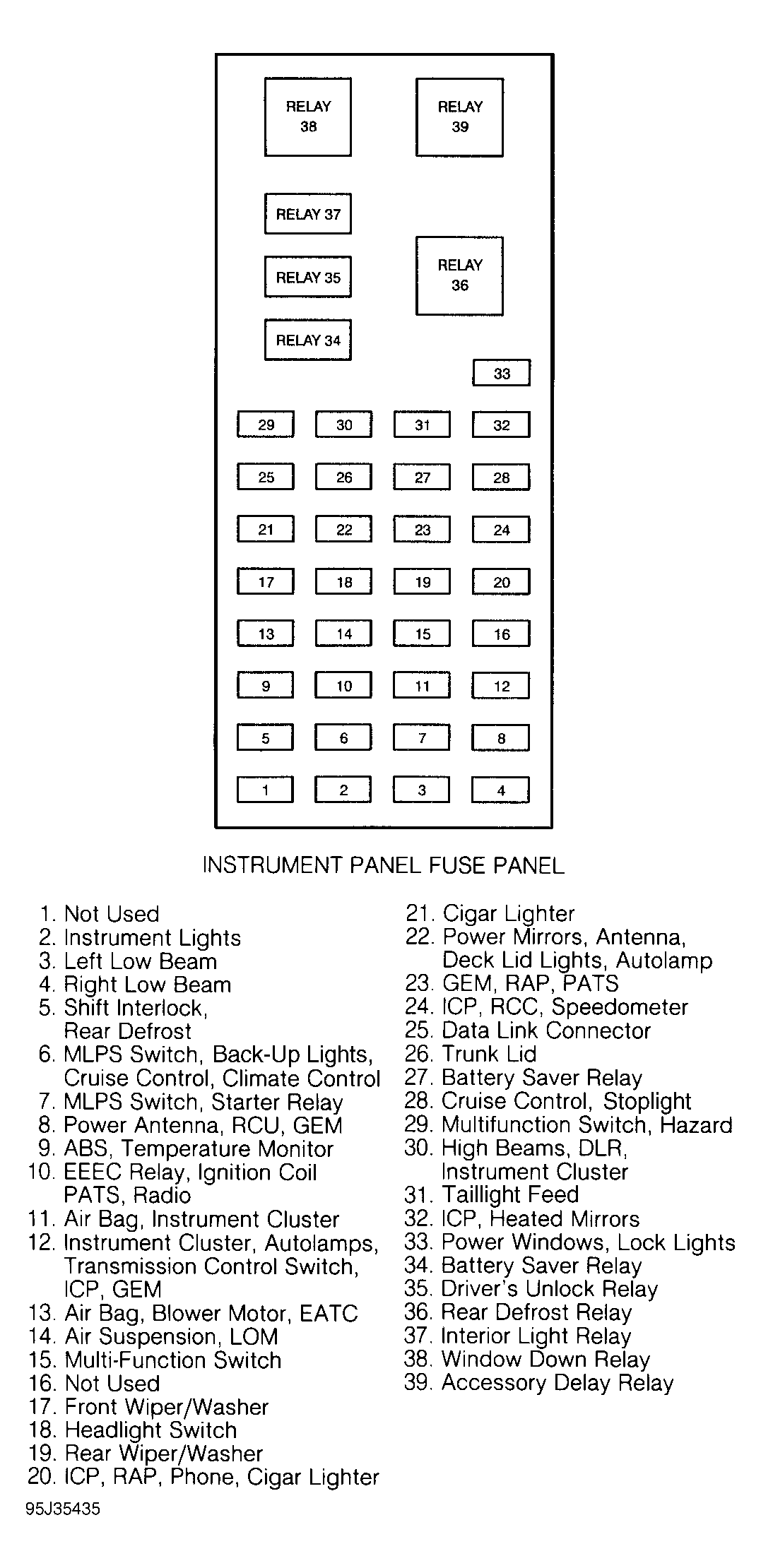
- Remove fuse No. 23 from fuse panel. See Fig 1
. Measure resistance between output pin (right side) of fuse No. 23 and ground. While observing ohmmeter, resistance should start at more than one M/ohm and drop steadily to less than 3 k/ohms. If resistance is as specified, go to step 7). If resistance is not as specified, go to next step.
- If resistance in step 1) read less than 10 ohms, go to step 4). If resistance was more than 10 ohms, go to next step.
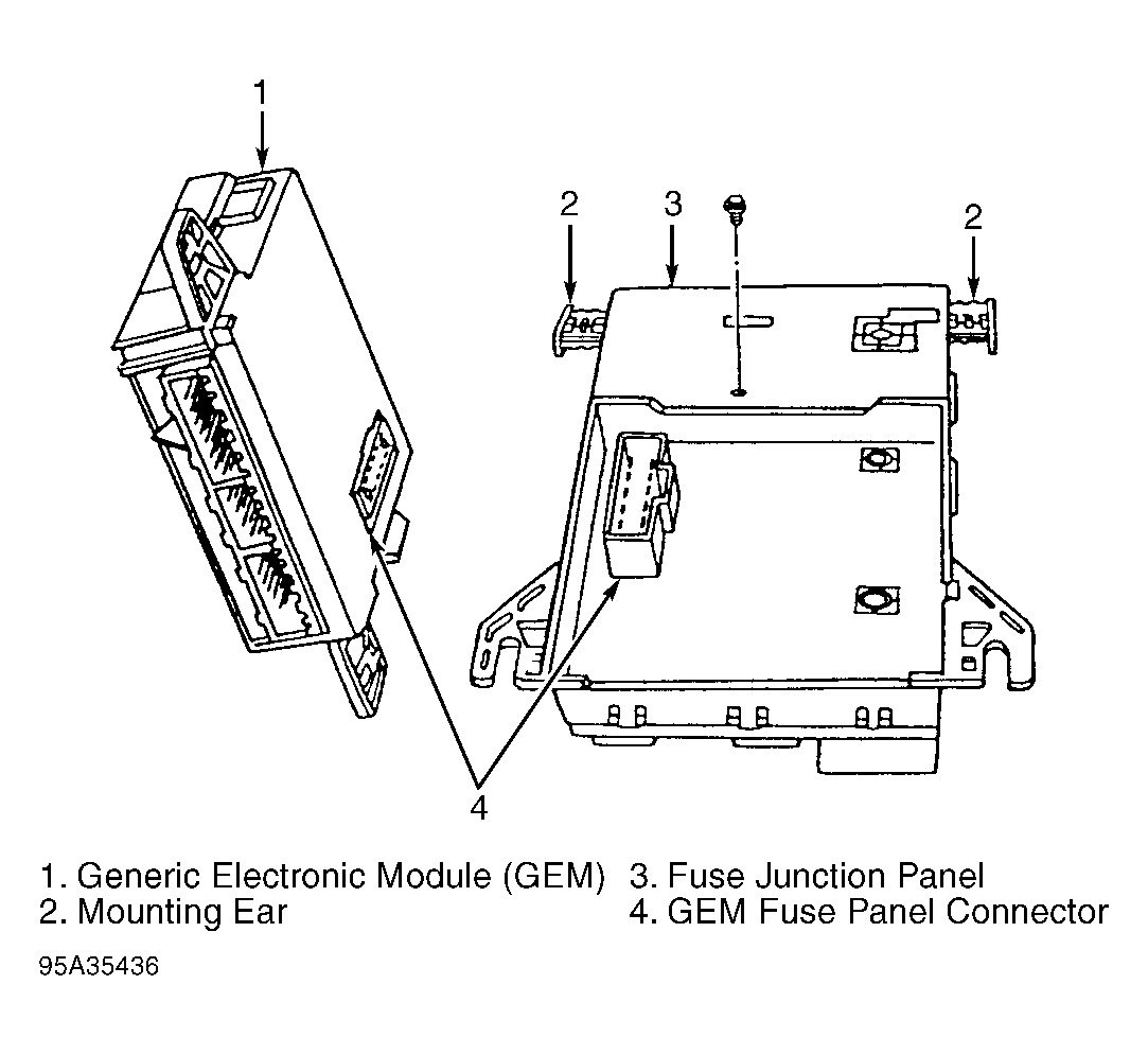
- Remove GEM from fuse junction box. See Fig 2
. Disconnect and reconnect ohmmeter as in step 1). If resistance is more than one M/ohm (may drop steadily to less than 3 k/ohms), replace GEM and retest. If resistance is not more than one M/ohm, go to next step.
- Disconnect fuse panel 27-pin connector C247. C247 is located on left side of instrument fuse panel. Measure resistance between output side of fuse No. 23 and ground. If resistance is less than 10 k/ohms, replace fuse junction panel and retest. If resistance is more than 10 k/ohms, reconnect fuse panel connector and go to next step if equipped with anti-theft system. If not equipped with anti-theft system, reconnect fuse panel connector and go to step 7).
- If equipped with Passive Anti-Theft System (PATS), disconnect PATS module connector located under center of dashboard. Disconnect and reconnect ohmmeter as in step 1). If resistance reads more than one M/ohm and drops steadily to less than 3 k/ohms, replace PATS module and retest. If resistance is not as specified, go to next step.
- If equipped with Remote Anti-Theft Personality (RAP), disconnect RAP module connector located under center of dashboard. Disconnect and reconnect ohmmeter as in step 1). If resistance reads more than one M/ohm, replace RAP module and retest. If resistance reads less than one M/ohm, repair circuit No. 1001 (White/Yellow wire) between fuse No. 23 and RAP module for short to ground and repeat test.
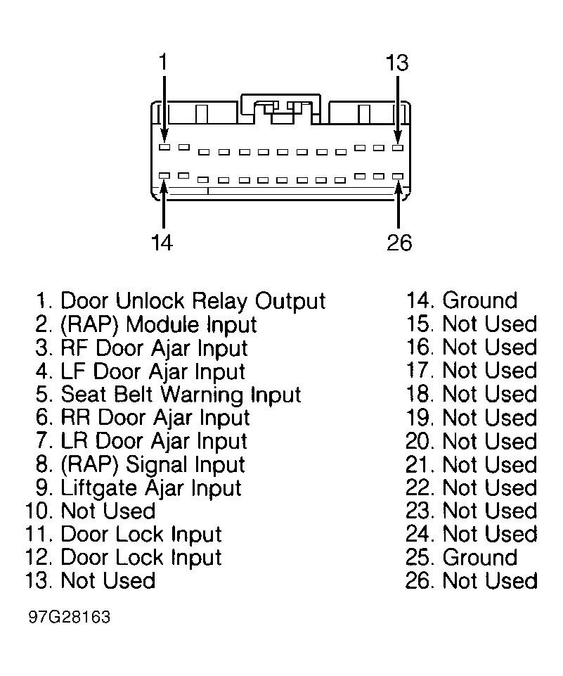
- Disconnect GEM connector C248. See Fig 3
- Fig 5
. Measure resistance from ground to GEM connector C248 terminals No. 14 and 25 (Black wire). If resistance is 5 ohms or less, go to next step. If resistance is more than 5 ohms, repair both circuit No. 57 (Black wire) for opens or high resistance and retest.
- Disconnect GEM connector C223. See Fig 3
- Fig 5
. Measure resistance from ground to GEM connector C223 terminal No. 12 (Black/White wire). If resistance is 5 ohms or less, go to next step. If resistance is more than 5 ohms, repair circuit No. 570 (Black/White wire) for open or high resistance and retest.
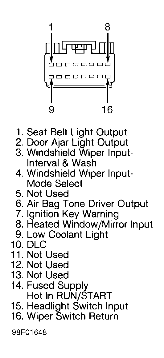
- Disconnect GEM connector C236. See Fig 3
- Fig 5
. Turn ignition switch to RUN position. Measure voltage between ground and GEM connector C236 terminal No. 14 (Red/Yellow wire). If battery voltage is present, go to step 11). If voltage is not present, go to next step.
- Remove fuse No. 12. See Fig 1
. Measure resistance across fuse. If fuse tests okay, repair circuit No. 640 (Red/Yellow wire) between fuse panel and GEM for open and retest. If fuse is blown, repair circuit No. 640 (Red/Yellow wire) between fuse panel and GEM for short to ground, replace fuse and retest.
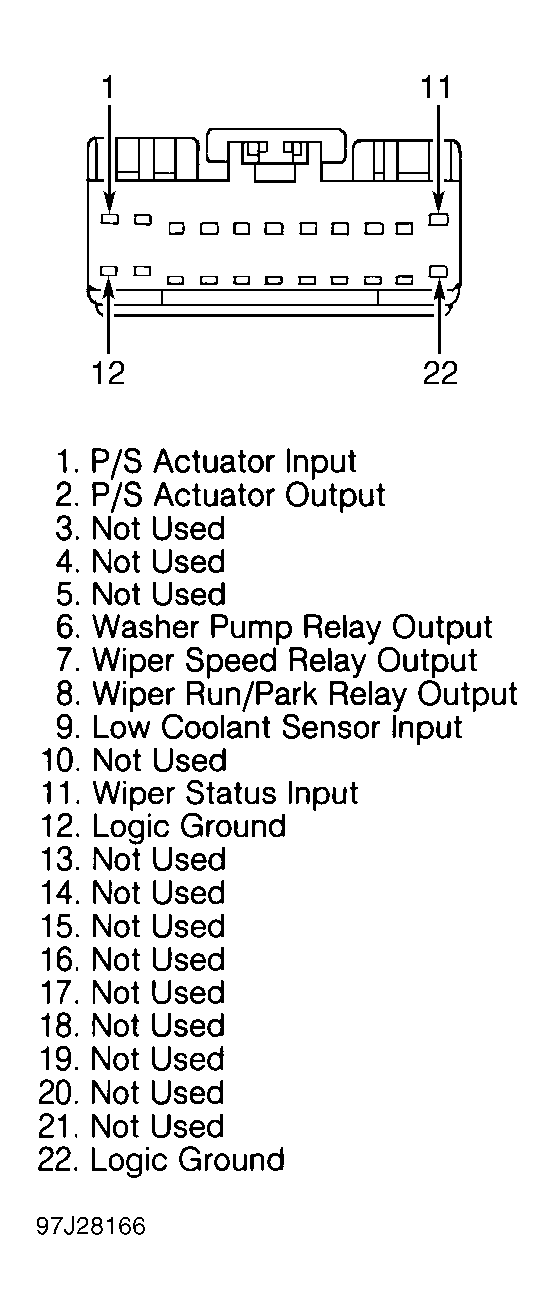
- Measure resistance between ground and GEM connector C223 terminal No. 22, circuit No. 938 (Black/Light Green wire). See Fig 3
- Fig 5
. If resistance is less than 5 ohms, trace, test and repair module communications network circuit No. 70 (Light Blue/White wire). See WIRING DIAGRAMS. If resistance is more than 5 ohms, repair circuit No. 938 (Black/Light Green wire).
 Courtesy of FORD MOTOR CO.
 Courtesy of FORD MOTOR CO.
 Courtesy of FORD MOTOR CO.
 Courtesy of FORD MOTOR CO.
 Courtesy of FORD MOTOR CO.