Speed Control Indicator Never/Always On
- Test drive vehicle and operate vehicle. If speed control operates properly, go to next step. If speed control does not operate properly, see CRUISE CONTROL SYSTEM article.
- Turn ignition off. Disconnect speed control servo connector. Speed control servo is located in right rear of engine compartment. Turn ignition on. Connect jumper wire between ground and speed control servo connector terminal No. 1 (Orange/Light Blue wire). See Fig 1
. Cycle headlight switch off and back on. If speed control indicator illuminates, replace speed control servo. See appropriate CRUISE CONTROL SYSTEM article. If speed control indicator does not illuminate with headlight switch in on or off position, go to step 5). If speed control indicator does not illuminate with headlight switch in off position, go to step 4). If speed control indicator does not illuminate, with headlight switch in on position, go to next step.
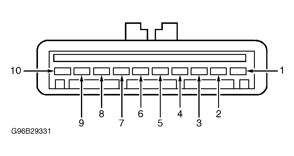
- Turn ignition off. Disconnect headlight switch connector. Turn ignition on. Rotate headlight switch dimmer wheel to full bright position. Measure voltage between ground and headlight switch connector terminal No. 9 (Light Blue/Red wire). See Figure
. If voltage is more than 10 volts, replace headlight switch. If voltage is 10 volts or less, repair open in Light Blue/Red wire between headlight switch connector and fuse No. 11.
- Turn ignition off. Disconnect headlight switch connector. Turn ignition on. Measure voltage between ground and headlight switch connector terminal No. 4 (Red/Yellow wire). If voltage is more than 10 volts, replace headlight switch. If voltage is 10 volts or less, repair open in Red/Yellow between headlight switch connector and instrument illumination dimming module near headlight switch.
- Turn ignition off. Disconnect headlight switch connector. Turn ignition on. Measure voltage between ground and headlight switch connector terminal No. 4 (Red/Yellow wire). If voltage is more than 10 volts, reconnect headlight switch and go to next step. If voltage is 10 volts or less, repair open in Red/Yellow between headlight switch connector and instrument illumination dimming module near headlight switch.
- Turn ignition off. Remove instrument cluster connector C214. See INSTRUMENT CLUSTER
under REMOVAL & INSTALLATION. Measure voltage between ground and instrument cluster connector C214 terminal No. 5 (Orange/Black wire). See Figure
. If voltage is more than 10 volts, go to step 8). If voltage is 10 volts or less, go to next step.
- Turn ignition off. Disconnect headlight switch connector. measure resistance of Orange/Black wire between instrument cluster connector C214 terminal No. 5 and headlight switch connector terminal No. 8. If resistance is less than 5 ohms, replace headlight switch. If resistance is 5 ohms or more, repair open Orange/Black wire.
- Disconnect speed control servo connector. Measure resistance of Orange/Light Blue wire between instrument cluster connector C214 terminal No. 4 and speed control servo connector terminal No. 1. See Figure
and Fig 1
. If resistance is less than 5 ohms, go to next step. If resistance is 5 ohms or more, repair open Orange/Light Blue wire.
- Check for continuity between charge indicator bulb terminals of printed circuit. See PRINTED CIRCUIT
under REMOVAL & INSTALLATION. If continuity exists, replace printed circuit. If continuity does not exist, replace bulb.
 Courtesy of FORD MOTOR CO.