Overdrive (O/D) Off Indicator Inoperative
- Test drive vehicle and verify O/D operation. If O/D operates properly, go to next step. If O/D does not operate properly, see TRANSMISSION SERVICING article in the AUTOMATIC TRANS SERVICE section.
- Turn ignition off. Install EEC-V 104-Pin Breakout Box (014-00950) following manufacturer's instructions. Turn ignition on. Connect jumper wire between Breakout Box pins No. 24 and 79. Cycle headlight switch off and back on. If O/D off indicator illuminates, see appropriate AUTO TRANS DIAGNOSIS article in the AUTO TRANS DIAGNOSIS section. If O/D off indicator does not illuminate with headlight switch in on or off position, go to step 5). If O/D off indicator does not illuminate with headlight switch in off position, go to step 4). If O/D off indicator does not illuminate, with headlight switch in on position, go to next step.
- Turn ignition off. Disconnect headlight switch connector. Turn ignition on. Rotate headlight switch dimmer wheel to full bright position. Measure voltage between ground and headlight switch connector terminal No. 9 (Light Blue/Red wire). See Fig 1
. If voltage is more than 10 volts, replace headlight switch. If voltage is 10 volts or less, repair open in Light Blue/Red wire between headlight switch connector and fuse No. 11.
- Turn ignition off. Disconnect headlight switch connector. Turn ignition on. Measure voltage between ground and headlight switch connector terminal No. 4 (Red/Yellow wire). If voltage is more than 10 volts, replace headlight switch. If voltage is 10 volts or less, repair open in Red/Yellow between headlight switch connector and instrument illumination dimming module near headlight switch.
- Turn ignition off. Disconnect headlight switch connector. Turn ignition on. Measure voltage between ground and headlight switch connector terminal No. 4 (Red/Yellow wire). If voltage is more than 10 volts, reconnect headlight switch and go to next step. If voltage is 10 volts or less, repair open in Red/Yellow wire between headlight switch connector and instrument illumination dimming module near headlight switch.
- Turn ignition off. Remove instrument cluster connector C214. See INSTRUMENT CLUSTER
under REMOVAL & INSTALLATION. Measure voltage between ground and instrument cluster connector C214 terminal No. 5 (Orange/Black wire). See Figure
. If voltage is more than 10 volts, go to step 8). If voltage is 10 volts or less, go to next step.
- Turn ignition off. Disconnect headlight switch connector. Measure resistance of Orange/Black wire between instrument cluster connector C214 terminal No. 5 and headlight switch connector terminal No. 8. If resistance is less than 5 ohms, replace headlight switch. If resistance is 5 ohms or more, repair open Orange/Black wire.
- Disconnect Powertrain Control Module (PCM). PCM is located at right rear of engine compartment. Install breakout box following manufacturer's instructions. Measure resistance between instrument cluster connector C214 terminal No. 1 (White/Light Green wire) and breakout box test pin No. 79. See Figure
. If resistance is less than 5 ohms, go to next step. If resistance is 5 ohms or more, repair open White/Light Green wire.
- Check for continuity between charge indicator bulb terminals of printed circuit. If continuity exists, replace printed circuit. See PRINTED CIRCUIT
under REMOVAL & INSTALLATION. If continuity does not exist, replace bulb.
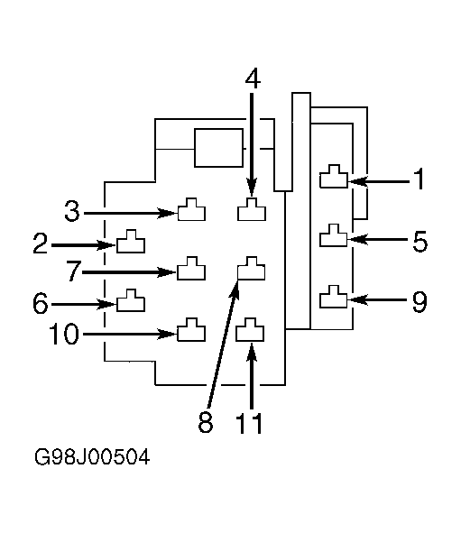 Courtesy of FORD MOTOR CO.