Fuel Level Reads Inaccurately
- Turn ignition on. Measure voltage between ground and load side of fuse No. 11 located in instrument panel fuse panel. If voltage is more than 10 volts, go to step 3). If voltage is less than 10 volts, go to next step.
- Measure voltage between ground and feed side of fuse No. 11 located in instrument panel fuse panel. If voltage is more than 10 volts, replace fuse and retest system. If voltage is less than 10 volts, repair wiring to fuse. See WIRING DIAGRAMS
.
- Remove instrument cluster. See INSTRUMENT CLUSTER
under REMOVAL & INSTALLATION. Turn ignition on. Measure voltage between ground and instrument cluster connector C215 terminal No. 2 (Red/Yellow wire). See Fig 1
. If voltage is more than 10 volts, go to next step. If voltage is less than 10 volts, repair open in Red/Yellow wire. See WIRING DIAGRAMS.
- Turn ignition off. Measure resistance between ground and instrument cluster connector C215 terminal No. 2 (Black/White wire). See Fig 1
. If resistance is less than 5 ohms, go to next step. If resistance is more than 5 ohms, repair open in Black/White wire. See WIRING DIAGRAMS
.
- Ensure ignition is off. Disconnect fuel gauge sending unit. Measure resistance between ground and fuel level sensor connector terminal No. 8 (Black/Yellow wire). See Fig 2
. If resistance is less than 5 ohms, reconnect instrument cluster and go to next step. If resistance is more than 5 ohms, repair open in Black/Yellow wire. See WIRING DIAGRAMS
.
- Using Instrument Gauge System Tester (014-R-1063), connect one tester lead to fuel sending unit connector terminal No. 5 (Yellow/White wire). Connect second lead to ground. Set tester to 22 ohms. Turn ignition on. Turn instrument gauge system tester on. Wait one minute and read fuel gauge. If fuel gauge reads "E", go to step 8). If gauge does not read "E", disconnect tester and go to next step.
- Turn ignition off. Remove instrument cluster. See INSTRUMENT CLUSTER
under REMOVAL & INSTALLATION. Measure resistance of Yellow/White wire between instrument cluster connector C215 terminal No. 12 and fuel level sensor connector terminal No. 5. See Fig 1
and Fig 2
. If resistance is less than 10 k/ohms, go to step 10). If resistance is more than 10 k/ohms, repair open in Yellow/White wire. See WIRING DIAGRAMS
.
- Turn ignition off. Set instrument gauge system tester to 145 ohms. Turn ignition on. Wait one minute and read fuel gauge. If fuel gauge reads "F", replace fuel level sensor. If gauge does not read "F", disconnect tester and go to next step.
- Turn ignition off. Disconnect instrument cluster connector C215. Measure resistance between ground and instrument cluster connector C215 terminal No. 2 (Yellow/White wire). See Fig 1
. If resistance is less than 5 ohms, repair short to ground in Yellow/White wire. See WIRING DIAGRAMS
. If resistance is more than 5 ohms, go to next step.
- Check printed circuit by making appropriate measurements. See FUEL GAUGE PRINTED CIRCUIT MEASUREMENTS table. If all resistance values are less than 5 ohms, replace fuel gauge and instrument cluster gauge amplifier. If resistance in any circuit measurement is 5 ohms or more, replace instrument cluster printed circuit.
FUEL GAUGE PRINTED CIRCUIT MEASUREMENTS
| Connector/Terminal |
Connector/Terminal |
| Fuel Gauge/"S" |
Gauge Amplifier |
| Fuel Gauge/"G" |
C215/2 |
| Fuel Gauge/"B" |
C215/8 |
| Fuel Gauge/Ground |
Gauge Amplifier |
| Gauge Amplifier |
C215/2 |
| Gauge Amplifier |
C215/12 |
| Gauge Amplifier |
C216/1 |
| Gauge Amplifier |
C215/3 |
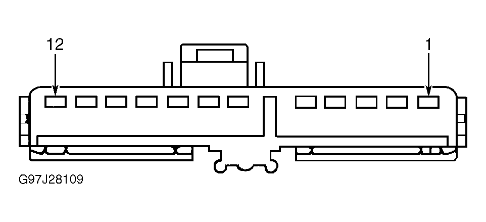 Courtesy of FORD MOTOR CO.
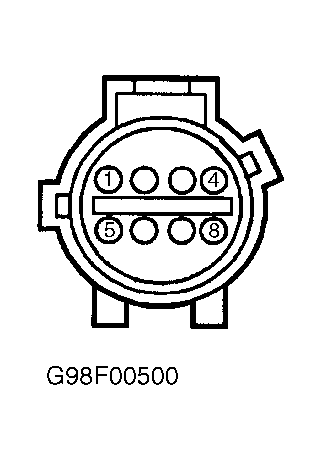 Courtesy of FORD MOTOR CO.
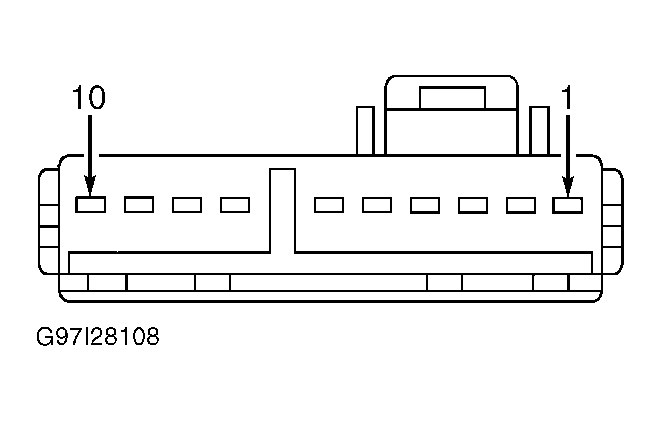 Courtesy of FORD MOTOR CO.