Tachometer Inaccurate
- Turn ignition off. Partially remove instrument cluster to access cluster connectors. See INSTRUMENT CLUSTER under REMOVAL & INSTALLATION. Turn ignition on. Check for battery voltage at instrument cluster connector C251 terminal No. 10 (Red/Yellow wire). See Figure
and Figure
. If battery voltage is present, go to next step. If battery voltage is not present, repair circuit No. 640 (Red/Yellow wire) and/or fuse No. 15 for open and retest system. See Figure
.
- Measure resistance between ground and instrument cluster connector C251 terminal No. 7 (Black/White wire). If resistance is 5 ohms or less, go to next step. If resistance is more than 5 ohms, repair circuit No. 397 (Black/White wire), circuit No. 59 (Black wire) or circuit No. 651 (Black/Yellow wire) for open and retest system.
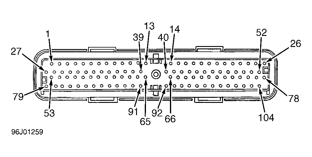
- Turn ignition off. Disconnect cluster connector C251. Install EEC-V 104-pin Breakout Box (014-00950) to PCM connector, following manufacturer's instructions. See Fig 1
. With an ohmmeter, measure resistance of circuit No. 659 (Orange/White wire) from breakout box terminal No. 48 to cluster connector C251 terminal No. 8 (Tan/Yellow wire). If resistance is 1.8 ohms or less, go to next step. If resistance is more than 1.8 ohms, repair circuit Orange/White wire and/or Tan/Yellow wire for open and retest system.
- Reconnect instrument cluster connector C251. Check resistance between tachometer connector clips to instrument cluster printed circuit. If resistance is less than 0.2 ohm, go to next step. If resistance is more than 0.2 ohm, replace connector clips and retest system.
- Using an ohmmeter, check continuity between instrument cluster gauge clips and indicated cluster terminals at connector C251. Use INSTRUMENT CLUSTER TERMINAL IDENTIFICATION table to identify cluster terminals to be tested. If there is continuity at all circuits, replace speedometer/tachometer assembly and retest system. If continuity is not present at all circuits, replace instrument cluster printed circuit and retest system.
INSTRUMENT CLUSTER TERMINAL IDENTIFICATION
| Terminal No. |
Harness Wire Color |
| 7 |
BLK/WHT |
| 8 |
(TAN/YEL) |
| 9 |
(BLK/YEL) |
| 10 |
(RED/YEL) |
 Courtesy of FORD MOTOR CO.