Integrated Circuit Display(S) Inoperative Or Erratic
- Using a voltmeter, verify battery voltage at output side (Red/Yellow wire) of fuse No. 15 (10-amp) located in instrument panel fuse panel. See Figure
. If battery voltage is present, go to step 3). If battery voltage is not present, go to next step.
- Using a voltmeter, verify battery voltage at input side of fuse No. 15. If battery voltage is present, replace fuse and retest system. If battery voltage is not present, repair supply circuit to fuse and retest system.
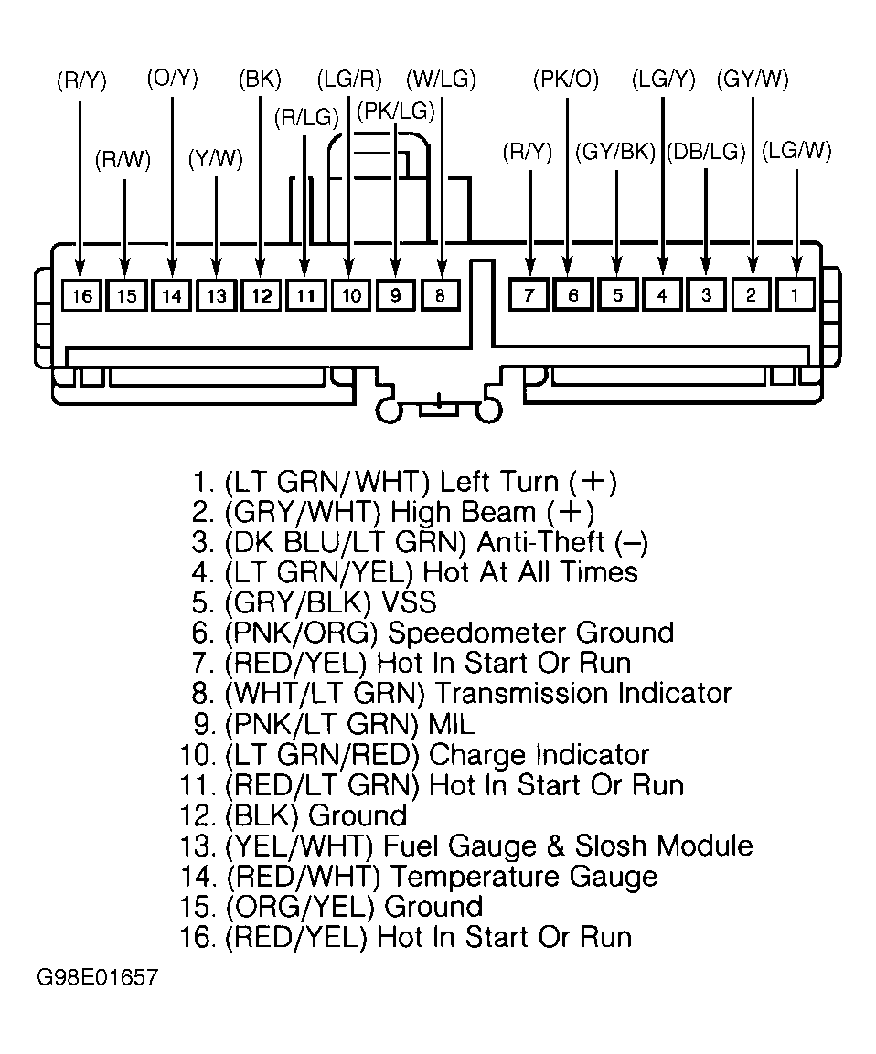
- Disconnect negative battery cable. Remove instrument cluster. See INSTRUMENT CLUSTER under REMOVAL & INSTALLATION. Disconnect instrument cluster connectors C250 and C251. See Fig 1
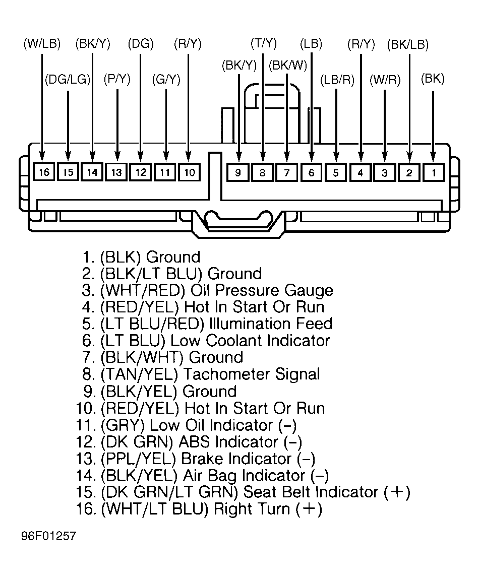
and Fig 2
. Reconnect negative battery cable and turn ignition switch to RUN position. Check for battery voltage at cluster connector C250 terminals No. 16 and 7 and connector C251 terminals No. 10 and 4. If battery voltage is present at all circuits, go to step 5). If battery voltage is not present at all circuits, go to next step.
- Remove fuse No. 15. Measure resistance of circuit No. 640 (Red/Yellow wire) between output side of fuse No. 15 and instrument cluster connector C250 terminals No. 16 (Red/Yellow wire) and No. 7 (Red/Yellow wire), and cluster connector C251 terminals No. 10 (Yellow/Red wire) and No. 4 (Red/Yellow wire). If resistance is less than one ohm, go to next step. If resistance is more than one ohm, repair open in circuit(s) in question and retest system.
- Measure resistance between ground and instrument cluster connector C250 terminals No. 16 (Red/Yellow wire) and No. 7 (Red/Yellow wire), and cluster connector C251 terminals No. 10 (Yellow/Red wire) and No. 4 (Red/Yellow wire). If resistance is more than 10 k/ohms, go to next step. If resistance is less than 10 k/ohms, repair short to ground in circuit(s) in question and retest system.
- Measure resistance between ground and instrument cluster connector C250 terminals No. 6 (Pink/Orange wire) and No. 15 (Orange/Yellow wire). Measure resistance between ground and instrument cluster connector C251 terminals No. 1 (Black wire), No. 2 (Black/Light Blue wire), No. 7 (Black/White wire) and No. 9 (Black/Yellow wire). If resistance is less than 5 ohms, replace instrument cluster printed circuit and retest. See PRINTED CIRCUIT under REMOVAL & INSTALLATION. If resistance is more than 5 ohms, repair open or high resistance in circuit(s) in question and retest system.
 Courtesy of FORD MOTOR CO.
 Courtesy of FORD MOTOR CO.