Charge Warning Never/Always On
- With ignition switch in OFF position, observe charge indicator light. If light is on, refer to generator diagnosis in appropriate GENERATOR article in the ELECTRICAL section. If light is off, go to next step.
- With engine off, turn ignition switch to RUN position and observe indicator light. If indicator light is on, go to next step. If indicator light is off, go to step 4).
- With engine running, observe charge indicator. If indicator is on, go to step 6). If indicator is off, test is complete and system operational.
- With ignition switch in RUN position and engine off, disconnect regulator connector and ground "I" terminal. See Fig 1
. If charge indicator is on, refer to generator diagnosis in appropriate GENERATOR article in the ELECTRICAL section. If indicator is off, remove ground wire and go to next step.
- Turn ignition off. Remove instrument cluster. see INSTRUMENT CLUSTER under REMOVAL & INSTALLATION. Measure resistance of Light Green/Red wire between regulator connector "I" terminal and instrument cluster connector C250 terminal No. 10. If resistance is less than one ohm, go to next step. If resistance is more than one ohm, repair circuit No. 904 (Light Green/Red wire) for open and retest system.
- Disconnect cluster connectors. Disconnect voltage regulator connector. Measure resistance between ground and cluster connector C250 terminal No. 10 (Light Green/Red wire). If resistance is 5 ohms or less, repair circuit No. 904 (Light Green/Red wire) for short and retest system. If resistance is more than 5 ohms, go to next step.
- Turn ignition on. Using a voltmeter, read voltage between ground and cluster connector C250 terminal No. 11 (Red/Light Green wire). If voltage reads 10 volts or more, go to next step. If voltage is less than 10 volts, repair circuit No. 16 (Red/Light Green wire) for open and retest system.
- Remove charge indicator light bulb and check continuity of bulb. If bulb is okay, replace instrument cluster printed circuit and retest system. If bulb is bad, replace bulb and retest system.
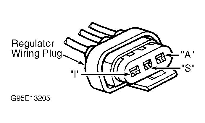 Courtesy of FORD MOTOR CO.