Test C: Temperature Gauge Inaccurate
- Test temperature gauge. See TEMPERATURE GAUGE
under COMPONENT TESTS. If temperature gauge is okay, replace temperature indicator sender. If temperature gauge is not okay, go to next step.
- Turn ignition off. Remove instrument cluster. See INSTRUMENT CLUSTER
under REMOVAL & INSTALLATION. Disconnect 3 instrument cluster electrical connectors. Measure voltage between ground and instrument cluster harness connector C252 terminal No. 3 (Black/Orange wire). See Figure
. If resistance is less than 5 ohms, go to next step. If resistance is more than 5 ohms, repair open in Black/Orange wire or White/Light Blue wire between instrument cluster connector and temperature indicator sender connector.
NOTE:
Black/Orange wire between instrument cluster connector and temperature indicator sender changes to White/Light Blue. See WIRING DIAGRAMS
.
- Measure resistance between ground and temperature indicator sender harness connector White/Light Blue wire. Resistance should be more than 10 k/ohms. If resistance is more than 10 k/ohms, go to next step. If resistance is not more than 10 k/ohms, repair White/Light Blue wire between temperature indicator sender harness connector and instrument cluster harness connector. See WIRING DIAGRAMS
.
- Turn ignition on. Measure voltage between ground and instrument cluster harness connector C254 terminal No. 6 (Black/Yellow wire). See Figure
. Voltage should be more than 10 volts. If voltage is more than 10 volts, go to next step. If voltage is less than 10 volts, repair Black/Yellow wire in question. See WIRING DIAGRAMS
.
- Turn ignition off. Measure resistance between ground and instrument cluster harness connector C254 terminal No. 5 (Black/Green wire). Resistance should be less than 5 ohms. If resistance is less than 5 ohms, go to next step. If resistance is more than 5 ohms, repair Black/Green wire in question. See WIRING DIAGRAMS
.
- Measure resistance between temperature gauge terminal "S" and temperature gauge terminal B+. Measure resistance between temperature gauge terminal "G" and temperature gauge terminal "S". Resistance should be 214-256 ohms between "S" and B+ terminals and 90-110 ohms between "G" and "S" terminals. If all resistance readings are as specified, replace instrument cluster printed circuit and gauge contact clips. See PRINTED CIRCUIT
under REMOVAL & INSTALLATION. If resistance readings are not as specified, replace fuel gauge. If vehicle is equipped with a fuel/temp assembly, replace gauge amplifier. See INSTRUMENT CLUSTER GAUGE AMPLIFIER
under REMOVAL & INSTALLATION.
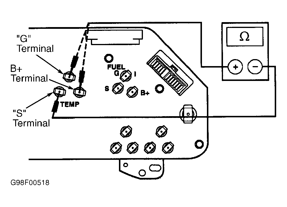 Courtesy of FORD MOTOR CO.