Warning Lights & Gauges Inoperative
- Disconnect negative battery cable. Remove instrument cluster.
See INSTRUMENT CLUSTER
under
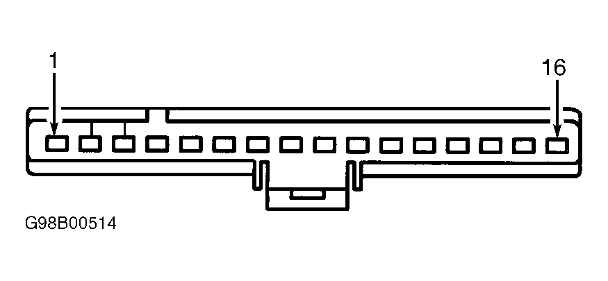
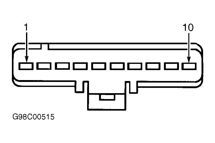
REMOVAL & INSTALLATION. Disconnect instrument cluster connectors C1
and C2. See Fig 1
and Fig 2
. Using an
ohmmeter, check for continuity of fuse No. 30 in instrument panel fuse
panel. See Fig 3
. If
fuse is blown, replace fuse and retest. If fuse blows again, go to
step 4). If continuity exists across fuse, go to next step.
- Turn ignition on. Measure voltage between ground and instrument
cluster connector C1 terminal No. 8 (Violet wire). If voltage is more
than 10 volts, go to next step. If voltage is less than 10 volts,
repair open in Violet wire.
- Turn ignition off. Measure resistance between ground and
instrument cluster connector C1 terminal No. 4 (Black wire) and
instrument cluster connector C2 terminal No. 7 (Black/Yellow wire). If
resistance is less than 5 ohms for both circuits, replace instrument
cluster printed circuit. See PRINTED
CIRCUIT
under REMOVAL & INSTALLATION. If resistance is more
than 5 ohms for either circuit, repair open in Black or Black/Yellow
wire.
- Measure resistance between ground and instrument cluster
connector C1 terminal No. 8 (Violet wire). Measure resistance between
ground and instrument cluster connector C1 terminal No. 4 (Black
wire). If resistance is more than 10 k/ohms for both circuits, replace
instrument cluster printed circuit. See
PRINTED CIRCUIT
under
REMOVAL & INSTALLATION. If resistance is 10 k/ohms or less for either
circuit, repair short to ground in Violet wire.
 Courtesy of FORD MOTOR CO.
 Courtesy of FORD MOTOR CO.
 Courtesy of FORD MOTOR CO.