Test F - Improper Brake Warning Operation
- Turn ignition off. Disconnect brake master cylinder fluid level sensor. Measure resistance between brake fluid level sensor terminals No. 1 and 2. See Fig 1
. With fluid level below MIN, resistance should be less than 5 ohms. With fluid level above MIN, resistance should be greater than 10 k/ohms. If resistances are as specified, go to next step. If resistances are not as specified, replace brake fluid level sensor.
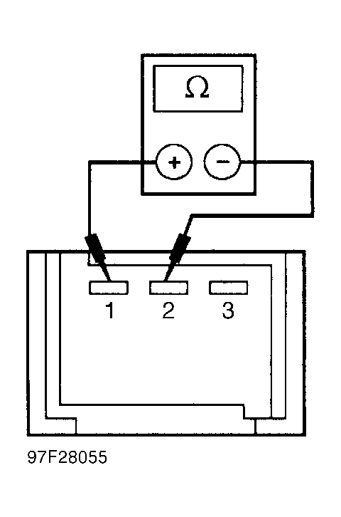 Courtesy of FORD MOTOR CO.
- Measure resistance between ground and brake master cylinder fluid level sensor harness connector Black wire. Resistance should be less than 5 ohms. If resistance is less than 5 ohms, go to next step. If resistance is greater than 5 ohms, repair Black wire between sensor harness connector and ground. See WIRING DIAGRAMS
.
- Turn ignition off. Remove instrument cluster. See INSTRUMENT CLUSTER
under REMOVAL & INSTALLATION. Disconnect instrument cluster electrical connector C1. See Figure
. Turn ignition on. Measure voltage between ground and instrument cluster harness connector C1, terminal No. 10 (Black/Yellow wire). Voltage should be greater than 10 volts. If voltage is greater than 10 volts, go to next step. If voltage is less than 10 volts, repair Black/Yellow wire between instrument cluster connector and fuse. See WIRING DIAGRAMS
.
- Turn ignition off. Disconnect parking brake signal switch connector. Measure resistance between ground and parking brake signal switch connector terminal. With parking brake engaged, resistance should be less than 5 ohms. With parking brake disengaged, resistance should be greater than 10 k/ohms. If resistances are as specified, go to next step. If resistances are not as specified, replace parking brake signal switch and bracket.
- Remove instrument cluster. See INSTRUMENT CLUSTER
under REMOVAL & INSTALLATION. Remove brake system warning light bulb. Check continuity between terminals of bulb. If continuity exists and concern is light never on, go to next step. If continuity exists and concern is light always on, go to step 8). If continuity does not exist, replace bulb.
- Turn ignition off. Disconnect instrument cluster harness connector C2. See Figure
. Disconnect brake master cylinder fluid level sensor connector. Disconnect parking brake signal switch or Daytime Running Lights (DRL) control connector (if equipped). Measure resistance between instrument cluster connector C2, terminal No. 3 (Green/Yellow wire) and brake master cylinder fluid level sensor connector Green/Yellow wire.
- Measure resistance between instrument cluster connector C2, terminal No. 3 (Green/Yellow wire) and parking brake signal switch Green/Yellow wire or DRL control connector (if equipped) Green/Yellow wire. Resistances in all tests should less than 5 ohms. If resistance is less than 5 ohms, go to next step. If resistance is greater than 5 ohms, repair Green/Yellow wire in question. See WIRING DIAGRAMS
.
- Measure resistance between ground and instrument cluster harness connector C2, terminal No. 3 (Green/Yellow wire). See Figure
. Resistance should be greater than 10 k/ohms. If resistance is greater than 10 k/ohms and vehicle is equipped with DRL, see appropriate DAYTIME RUNNING LIGHTS article. If resistance is greater than 10 k/ohms and vehicle is not equipped with DRL, replace instrument cluster gauge amplifier. See INSTRUMENT CLUSTER GAUGE AMPLIFIER
under REMOVAL & INSTALLATION. If resistance is less than 10 k/ohms, repair Green/Yellow wire. See WIRING DIAGRAMS
.