Test B - Fuel Gauge Inaccurate
- Test fuel gauge. See FUEL GAUGE
under COMPONENT TESTS. If fuel gauge is okay, go to next step. If fuel gauge tests bad, replace fuel gauge.
- Test fuel level sensor. See FUEL LEVEL SENSOR
under COMPONENT TESTS. If fuel level sensor is okay, repair Black/Green wire between ground and fuel level sensor harness connector. See WIRING DIAGRAMS. If level sensor tests bad, replace fuel level sensor. If problem is not resolved, go to next step.
- Turn ignition off. Remove instrument cluster. See INSTRUMENT CLUSTER
under REMOVAL & INSTALLATION. Disconnect instrument cluster harness connector C1. See Figure
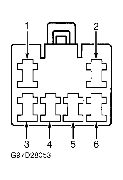
. Measure resistance between ground and instrument cluster harness connector C1, terminal No. 5 (Black/Green wire). Resistance should be less than 5 ohms. If resistance is less than 5 ohms, go to next step. If resistance is more than 5 ohms, repair open in Black/Green wire between instrument cluster harness connector and ground. See WIRING DIAGRAMS
.
- Turn ignition off. Disconnect fuel level sensor and pump connector. Measure resistance of Yellow/Brown wire between instrument cluster harness connector C1, terminal No. 4 and fuel level sensor and pump harness connector terminal No. 3. See Figure
and Figure
. Resistance should be less than 5 ohms. If resistance is less than 5 ohms, go to next step. If resistance is more than 5 ohms, repair open in Yellow/Brown wire. See WIRING DIAGRAMS
.
 Courtesy of FORD MOTOR CO.
- Turn ignition off. Disconnect instrument cluster harness connector C2. Turn ignition on. Measure voltage between ground and instrument cluster harness connector terminal No. 4 (Black/Yellow wire). See Figure
. Voltage should be greater than 10 volts. If voltage is greater than 10 volts, go to next step. If voltage is less than 10 volts, repair Black/Yellow wire between METER fuse and instrument cluster harness connector. See WIRING DIAGRAMS
.
- Visually inspect instrument cluster printed circuit for damage, cracks or hot spots. If instrument cluster printed circuit is okay, go to next step. If instrument cluster printed circuit is damaged, replace printed circuit and gauge contact clips. See PRINTED CIRCUIT
under REMOVAL & INSTALLATION.
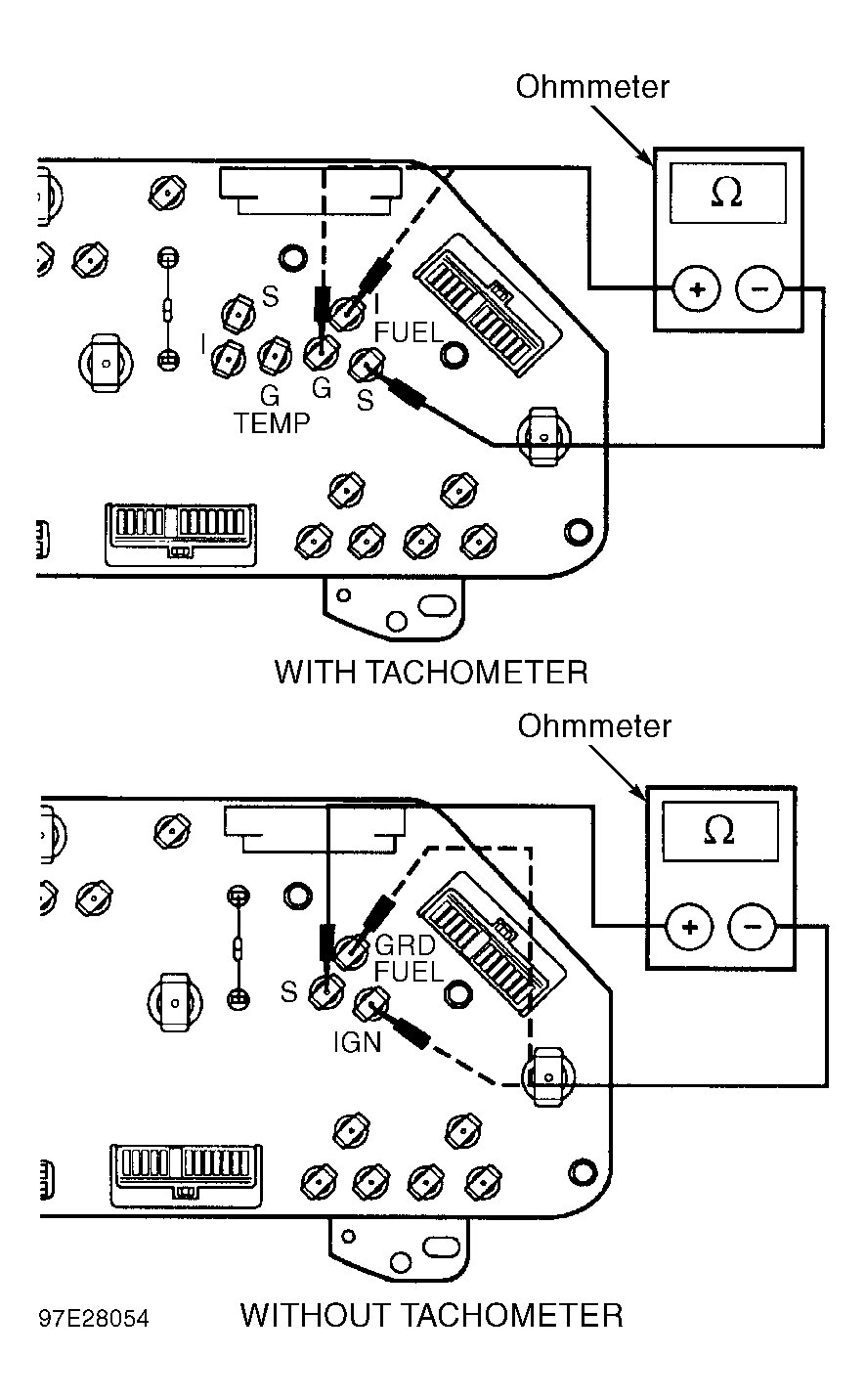
- Move instrument cluster to work surface. Measure resistance between instrument cluster fuel gauge terminals "S" and "G" and between terminals "S" and "I". See Fig 2
. Resistance in both tests should be about 180 ohms. Remove fuel gauge from instrument cluster. See FUEL GAUGE
under REMOVAL & INSTALLATION.
- Measure resistance between fuel gauge terminal "S" and fuel gauge case. Measure resistance between fuel gauge terminal "G" and fuel gauge case. Measure resistance between fuel gauge terminal "I" and fuel gauge case. Resistance should be greater than 10 k/ohms. If all resistance readings are as specified, replace instrument cluster gauge amplifier. See INSTRUMENT CLUSTER GAUGE AMPLIFIER
under REMOVAL & INSTALLATION. If resistance readings are not as specified, replace fuel gauge.
 Courtesy of FORD MOTOR CO.