Fuel Level Reads Inaccurately
- Turn ignition on. Measure voltage between ground and load side of fuse No. 18 (Aerostar) or fuse No. 11 (Ranger) located in instrument panel fuse panel. If voltage is more than 10 volts, go to step 3). If voltage is less than 10 volts, go to next step.
- Measure voltage between ground and feed side of fuse No. 18 (Aerostar) or fuse No. 11 (Ranger) located in instrument panel fuse panel. If voltage is more than 10 volts, replace fuse and retest system. If voltage is less than 10 volts, repair wiring to fuse. See WIRING DIAGRAMS
.
- Partially remove instrument cluster leaving connectors connected. See appropriate INSTRUMENT CLUSTER
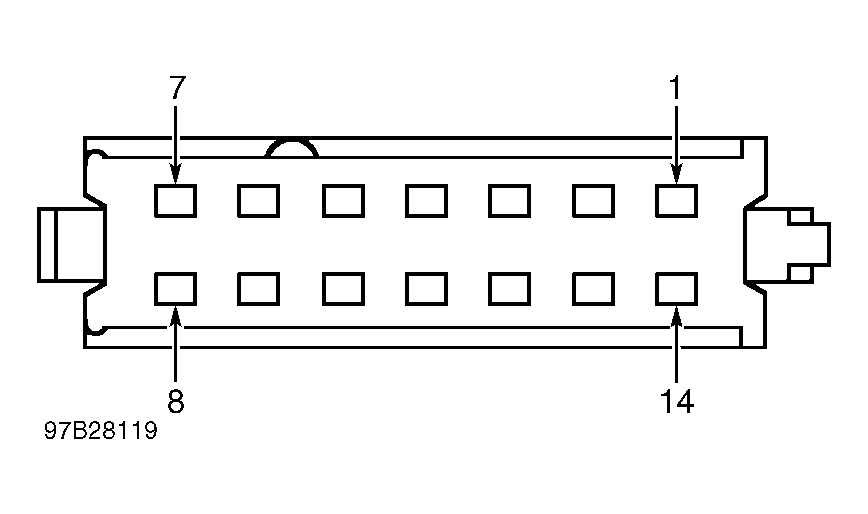
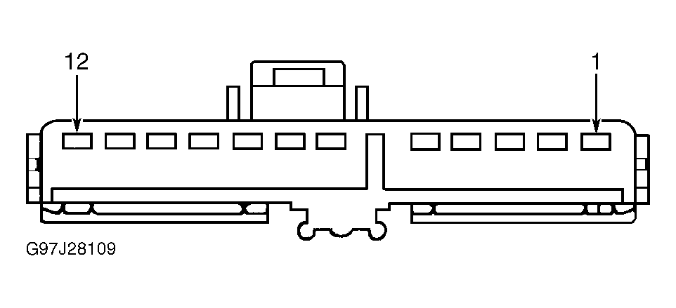
under REMOVAL & INSTALLATION. Turn ignition on. On Aerostar, measure voltage between ground and instrument cluster connectors C250, terminal No. 12 and C251, terminal No. 13 (all Red/Yellow wires). See Fig 1
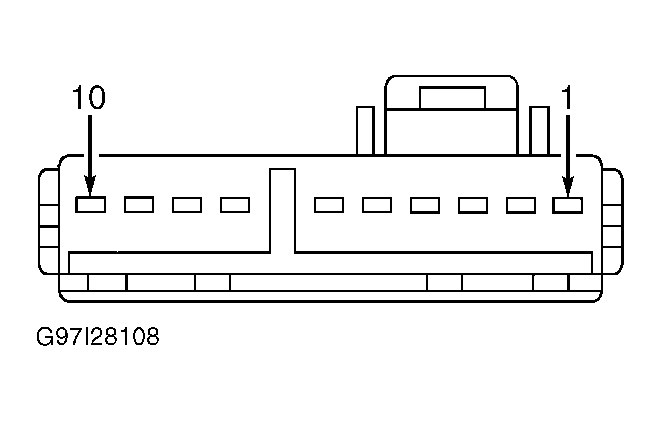
. On Ranger, measure voltage between ground and instrument cluster connectors C214, terminal No. 13, C215, terminal No. 8 and C216, terminal No. 1 (all Red/Yellow wires). See Fig 2
, Fig 3
and Fig 4
. If voltage is more than 10 volts, go to next step. If voltage is less than 10 volts, repair open in appropriate Red/Yellow wire. See WIRING DIAGRAMS
.
- Turn ignition off. On Aerostar, measure resistance between ground and instrument cluster connectors C250, terminal No. 13 and C251, terminal No. 9 (all Black/White wires). See Fig 1
. On Ranger, measure resistance between ground and instrument cluster connector C215, terminal No. 2 (Black/White wire). See Fig 3
. If resistance is less than one ohm, go to next step. If resistance is more than one ohm, repair open in appropriate Black/White wire. See WIRING DIAGRAMS
.
- Ensure ignition is off. Disconnect fuel gauge sending unit. Using Instrument Gauge System Tester (014-R-1063), connect one tester lead to fuel sending unit input wire (Yellow/White wire) at fuel gauge sending unit connector. Connect second lead to ground. Set tester to 22 ohms. Turn ignition on. Wait one minute and read fuel gauge. If fuel gauge reads "E", go to step 8). If gauge does not read "E", go to next step.
- Turn ignition off then on. Tap on instrument panel. Wait one minute and read fuel gauge. If fuel gauge reads "E", go to step 8). If gauge does not read "E", go to next step.
- Turn ignition off. Disconnect instrument cluster connectors and remove cluster gauge amplifier located on back of instrument cluster. Measure resistance of circuit between SIG terminal of fuel gauge and instrument cluster gauge amplifier. If resistance is less than one ohm, replace instrument cluster gauge amplifier and fuel gauge, and return to step 5). See GAUGES
under REMOVAL & INSTALLATION. On Aerostar, if resistance is more than one ohm, replace instrument cluster. See INSTRUMENT CLUSTER (AEROSTAR)
under REMOVAL & INSTALLATION. On Ranger, if resistance is more than one ohm, replace instrument cluster printed circuit. See PRINTED CIRCUIT (RANGER)
under REMOVAL & INSTALLATION.
- Turn ignition off. Disconnect instrument cluster connectors and fuel gauge sending unit connector. Measure resistance of Yellow/White wire between instrument cluster connector C251, terminal No. 6 (Aerostar) or connector C215, terminal No. 12 (Ranger) and fuel gauge sending unit connector. If resistance is less than one ohm, go to next step. If resistance is more than one ohm, repair open in Yellow/White wire between instrument cluster connector and fuel gauge sending unit connector.
- Ensure ignition is off. On Aerostar, measure resistance between ground and fuel gauge sending unit connector Black/White wire. On Ranger, measure resistance between ground and fuel gauge sending unit connector Black/Yellow wire. If resistance is less than one ohm, go to next step. If resistance is more than one ohm, repair open in Black/White or Black/Yellow wire.
- Ensure ignition is off. Using Instrument Gauge System Tester (014-R-1063), connect one tester lead to fuel sending unit input wire (Yellow/White wire) at fuel gauge sending unit connector. Connect second lead to ground. Set tester to 145 ohms. Turn ignition on. Wait one minute and read fuel gauge. If fuel gauge reads "F", go to next step. If gauge does not read "F", replace fuel gauge and gauge amplifier, and go to step 5). See GAUGES
under REMOVAL & INSTALLATION.
- Inspect fuel tank for distortion or damage. If fuel tank is damaged, replace fuel tank. If fuel tank is undamaged, go to next step.
- Connect one lead of ohmmeter to fuel tank sender signal lead (Yellow/White wire) and other ohmmeter lead to fuel tank sender ground (Black/White wire). If ohmmeter reads 14-18 ohms when float rod is closest to fuel filter (empty stop), leave ohmmeter connected and go to next step. If resistance is not 14-18 ohms, replace fuel tank sender.
- Position fuel tank sender float rod against full stop and observe ohmmeter. If resistance is 154-162 ohms, leave ohmmeter connected and go to next step. If resistance is not 154-162 ohms, replace fuel tank sender.
- Move fuel tank sender float rod slowly from full stop to empty stop. If resistance decreases slowly, go to next step. If resistance does not decrease slowly, replace fuel tank sender.
- Reconnect fuel tank sender connector to harness. Move fuel tank sender float rod to empty stop. Turn ignition on. Wait one minute and read fuel gauge. If fuel gauge reads "E", go to next step. If fuel gauge does not read "E", return to step 7).
- Move fuel tank sender float rod to full stop. Turn ignition on. Wait one minute and read fuel gauge. If fuel gauge reads "F", go to next step. If fuel gauge does not read "F", return to step 7).
- Inspect fuel tank sender float and float rod. If float or float rod is distorted, hitting filter, filled with fuel or loose, replace fuel tank sender. If float and float rod are okay, go to next step.
- Connect one ohmmeter lead to fuel sender signal lead (Yellow/White wire) in pigtail connector and the other ohmmeter lead to corresponding wire below flange rivet. Check ground circuit (Black/White wire) in the same manner. If resistance is more than one ohm, replace sending unit. If resistance is one ohm or less, pigtail is okay.
 Courtesy of FORD MOTOR CO.
 Courtesy of FORD MOTOR CO.
 Courtesy of FORD MOTOR CO.
 Courtesy of FORD MOTOR CO.