Displays Inoperative Or Erratic
- Disconnect negative battery cable. Remove instrument cluster. See INSTRUMENT CLUSTER
under REMOVAL & INSTALLATION. Disconnect cluster connectors C1 and C2. See Figure
.
- Remove fuse No. 30 from instrument panel fuse panel. See Fig 3
. Check continuity between load side of fuse No. 30 (Purple wire) and ground.
- If resistance is more than 10 k/ohms, go to next step. If resistance is less than 10 k/ohms, repair short to ground in circuit No. 14 (Purple wire).
- Measure resistance of circuit No. 14 (Purple wire) between load side of fuse No. 30 and cluster connectors C1, pin No. 9 (Purple wire) and C2, pin No. 5 (Purple wire). If resistance is less than 5 ohms for circuits, replace instrument cluster printed circuit. See PRINTED CIRCUIT
under REMOVAL & INSTALLATION. If resistance is more than 5 ohms for circuits, repair open in circuits as required.
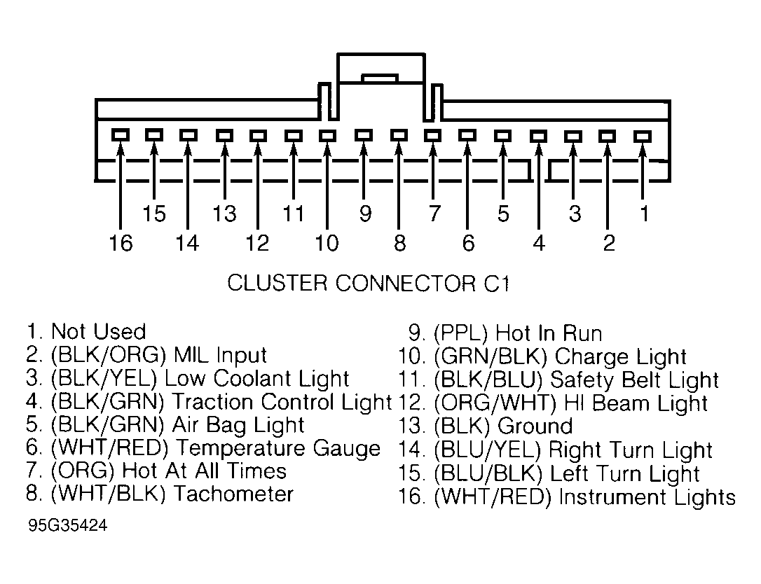 Courtesy of FORD MOTOR CO.
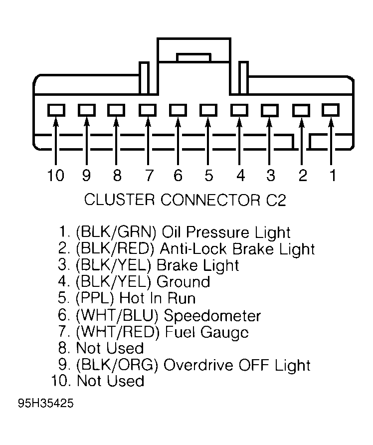 Courtesy of FORD MOTOR CO.
 Courtesy of FORD MOTOR CO.