Crown Victoria & Grand Marquis
- Unplug connectors from combination switch. Set hazard flasher switch to OFF position. If continuity is not as specified in the following tests, or is poor in any switch position, replace combination switch. See Fig 1.
- To test turn signal switch, perform steps 3) through 5). To test dimmer switch, perform steps 6) through 8). To test hazard flasher switch, perform steps 9) and 10). To test windshield wiper/washer switch, see appropriate WIPER/WASHER SYSTEMS article in the ACCESSORIES/SAFETY EQUIPMENT section.
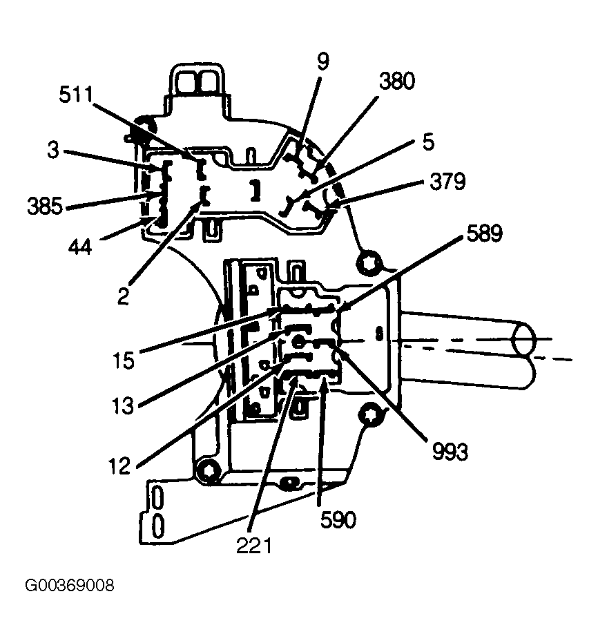 Courtesy of FORD MOTOR CO.
- Set turn signal lever to neutral position. Continuity should exist between terminals No. 5, 9, and 511. See Fig 1. Continuity should not exist between terminal No. 511 and terminals No. 2, 3, 44 and 385. Continuity should not exist between terminal No. 44 and terminals No. 2, 3, 5, 9 and 385. Continuity should not exist between terminal No. 385 and terminals No. 2 and 3. Continuity should not exist between terminal No. 15 and terminals No. 379 and 380, or between terminals No. 379 and 380.
- Set turn signal lever to left turn position. Continuity should exist between terminals No. 5 and 511. Continuity should exist between terminal No. 44 and terminals No. 3 and 9. Continuity should exist between terminals No. 15 and 380. Continuity should not exist between terminal No. 511 and terminals No. 3, 9, 44, and 385. Continuity should not exist between terminal No. 44 and terminals No. 2, 5, and 385. Continuity should not exist between terminals No. 2 and 385.
- Set turn signal lever to right turn position. Continuity should exist between terminals No. 9 and 511. Continuity should exist between terminal No. 44 and terminals No. 2 and 5. Continuity should not exist between terminal No. 511 and terminals No. 2, 5, 44, and 385. Continuity should not exist between terminal No. 44 and terminals No. 3, 9, and 385. Continuity should not exist between terminals No. 2 and 385.
- Pull and hold flash-to-pass switch toward steering wheel. With switch held in position, continuity should exist between terminals No. 12 and 196, and between terminals No. 13 and 15. See Fig 1.
- Set dimmer switch to high beam position (away from steering wheel). Continuity should exist between terminals No. 12 and 15.
- Set dimmer switch to low beam position (toward steering wheel). Continuity should exist between terminals No. 13 and 15.
- Press and release hazard flasher button to ON position. Set turn signal lever to neutral position. Continuity should exist between terminal No. 385 and terminals No. 2, 3, 5, and 9. See Fig 1.
- Press and release hazard flasher button to OFF position. Set turn signal lever to neutral position. Continuity should not exist between terminal No. 385 and terminals No. 2, 3, 5, or 9.