Lower Intake Manifold - Carbureted
Removal1. Drain the cooling system. Remove the air cleaner and intake duct assembly, including the crankcase ventilation hose.
2. Disconnect the accelerator cable and speed control linkage (if so equipped) from the carburetor. Remove the accelerator cable bracket. Disconnect the automatic transmission kickdown rod at the carburetor (if so equipped). Disconnect the electric choke and carburetor solenoid wires, if so equipped.
3. Disconnect the high-tension lead and wires from the coil
4. Disconnect the spark plug wires from the spark plugs by grasping, twisting and pulling the moulded cap. Remove the wires and bracket assembly from the rocker arm cover attaching stud. Remove the distributor cap and spark plug wires as an assembly.
5. Remove the carburetor fuel inlet line. Push-connect fittings.
6. Disconnect the distributor vacuum hoses from the distributor if so equipped or Electronic Engine Control (EEC) distributor connection. Remove the distributor hold down bolt and remove the distributor. Disconnect evaporative hoses.
7. Disconnect the radiator upper hose from the coolant outlet housing, and the water temperature sending unit wire at the sending unit. Remove the heater hose from the intake manifold.
8. Loosen the clamp on the water pump by-pass hose at the coolant outlet housing and slide the hose off the outlet housing.
9. Disconnect the crankcase vent hose at the valve rocker arm cover.
10. Remove the intake manifold and carburetor as an assembly. It may be necessary to pry the intake manifold away from the cylinder heads. Remove the intake manifold gaskets and seals. Discard the intake manifold attaching bolt sealing washers.
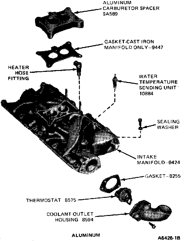
11. If the manifold assembly is to be disassembled, identify all vacuum hoses before disconnecting them. Remove the coolant outlet housing gasket and thermostat. Remove the ignition coil, temperature sending unit, carburetor, spacer, (on EEC engines remove Exhaust Gas Recirculation (EGR) cooler and related parts) gasket, vacuum fitting, accelerator retracting spring bracket and choke cable bracket.
Installation
1. If the intake manifold assembly was disassembled, install the temperature sending unit (threads coated with electrical conductive sealer), ignition coil, carburetor, spacer, (on EEC engine install EGR cooler and related parts) gaskets, vacuum fitting, accelerator retracting spring bracket and choke cable bracket. Position the thermostat in the coolant outlet housing. Coat the new thermostat gasket with water-resistant sealer such as Ford Perfect Seal or equivalent, and position it on the coolant outlet housing. Install the coolant outlet housing. Tighten to 13-16 N-m (9-12 ft-lbs). Connect all vacuum hoses.
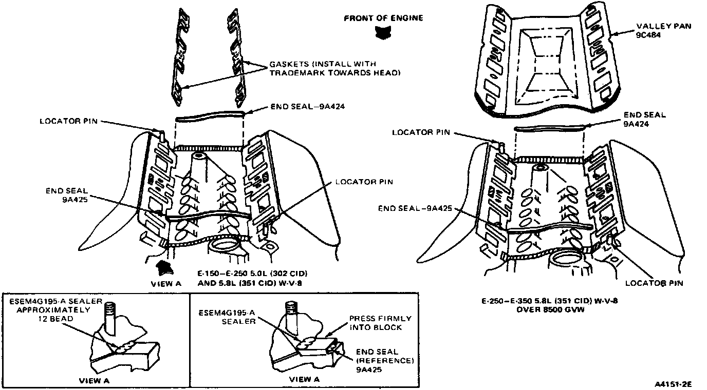
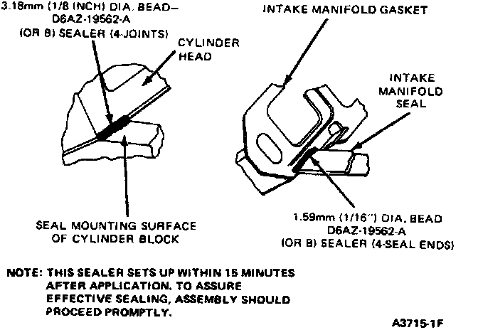
2. Clean the mating surfaces of the intake manifold, cylinder heads and cylinder block using a solvent such as Ford Spot Remover or equivalent. Apply a 3.2 mm (1/8 inch) bead of RTV sealer, at the points shown.
3. Apply a 1.6 mm (1/16 inch) bead of RTV sealer to the outer end of each intake manifold seal for the full width of the seal (4 places).
NOTE: This sealer sets-up in 15 minutes, so it is important that assembly be completed promptly. Do not drip any sealer into the engine valley.
Position the seals on the cylinder block and new gaskets on the cylinder heads with trademark towards cylinder head with the gaskets interlocked with the seal tabs. Be sure the holes in the gaskets are aligned with the holes in the cylinder heads.
4. Carefully lower the intake manifold into position on the cylinder block and cylinder heads.
NOTE: After the intake manifold is in place, run a finger around the seal area to make sure the seals are in place. If the seals are not in place, remove the intake manifold and position the seals.
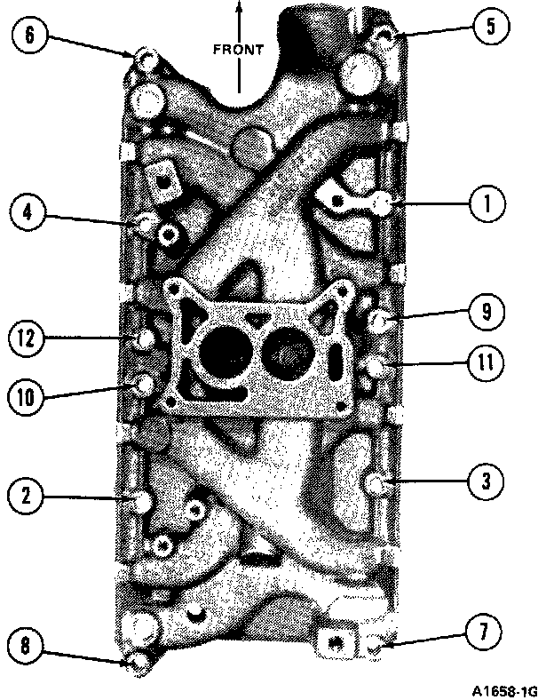
5. Be sure the holes in the manifold gaskets and manifold are in alignment. Install the intake manifold attaching nuts and bolts. Tighten all nuts and bolts in sequence to 32-33 N-m (23-25 ft-lbs).
NOTE: After completing the remaining assembly steps, operate the engine until it reaches normal operating temperature, then re-tighten the manifold nuts and bolts in sequence to 32-33 N-m (23-25 ft-lbs).
6. Install the water pump by-pass hose on the coolant outlet housing. Slide the clamp into position and tighten the clamp.
7. Connect the radiator upper hose. Install the heater hose and connect the hose to the intake manifold.
8. Install the fuel inlet line.
9. ROTATE the crankshaft damper until the No.1 piston is on Top Dead Center (TDC) at the end of the compression stroke. Install the distributor.
10. Install the distributor cap. Connect the spark plug wires and bracket assembly to attaching stud on rocker arm cover and connect the wires to the plugs.
11. Connect crankcase vent hose. Connect the high-tension lead and coil wires.
12. Connect accelerator cable and accelerator cable bracket. Connect speed control cable, if so equipped. Connect the choke cable. Connect electric choke and carburetor wires, if so equipped. Connect the automatic transmission kickdown rod/cable at the carburetor (if so equipped). Reconnect evaporative canister hoses.
13. Fill and bleed the cooling system.
WARNING: DO NOT OPERATE THE ENGINE WITH THE HOOD OPEN UNTIL THE FAN HAS BEEN FIRST EXAMINED FOR POSSIBLE CRACKS AND SEPARATION.
14. Start the engine and check and adjust the ignition timing. Connect the distributor vacuum hoses to the distributor, if so equipped.
15. Operate the engine at fast idle and check all hose connections and gaskets for leaks. Operate the engine until engine temperatures have stabilized and adjust the engine idle speed and idle fuel mixture to specifications on engine decal. Re-tighten the intake manifold bolts in sequence to 32-33 N-m (23-25 ft-lbs).
16. Adjust the transmission throttle linkage. Install the air cleaner and intake duct assembly, including the closed crankcase ventilation hose.