Lower Intake Manifold
Pre-Service ProceduresThe fuel charging assembly consists of the air throttle body, and the upper and lower intake manifolds. Prior to service or removal of the fuel charging assembly, the following steps must be taken:
1. Open hood and install protective covers.
2. Disconnect negative battery lead and secure it out of the way.
3. Remove fuel cap at tank pressure.
4. Release pressure from fuel system.
Removal
1. Remove intake manifold/throttle body assembly and air cleaner assembly must be removed prior to lower intake manifold removal.
2. Drain the coolant system.
3. Remove distributor assembly, cap and wires. Mark position of distributor and rotor during removal so that they can be installed in their original position.
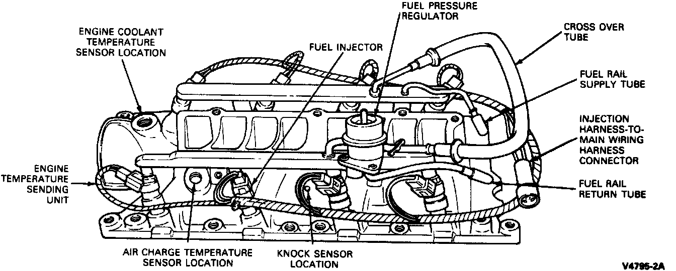
4. Disconnect the electrical connections at the Engine Coolant Temperature (ECT) Sensor, Engine Temperature Sending Unit, Air Charge Temperature (ACT) Sensor, and Knock Sensor (KS).
5. Disconnect the injector wiring harness from main harness assembly.
6. Remove Exhaust Gas Oxygen (EGO) sensor ground wire from intake manifold stud.
NOTE: The plated stud and ground wire must be Installed in the same position as which it was removed.
7. Disconnect fuel supply and return lines from fuel rails.
8. Remove upper radiator hose from thermostat housing.
9. Remove water bypass hose.
10. Remove heater outlet hose at intake manifold.
11. Remove air cleaner bracket by removing three attaching nuts. (Two nuts on intake manifold and one nut on exhaust manifold.)
12. Remove nut securing coil bracket and move bracket out of way.
13. Remove intake attaching bolts and studs, noting location of studs and bolts.
14. Remove lower intake manifold assembly.
Installation
1. Clean and inspect the mounting faces of the lower intake cylinder heads and cylinder block surfaces.
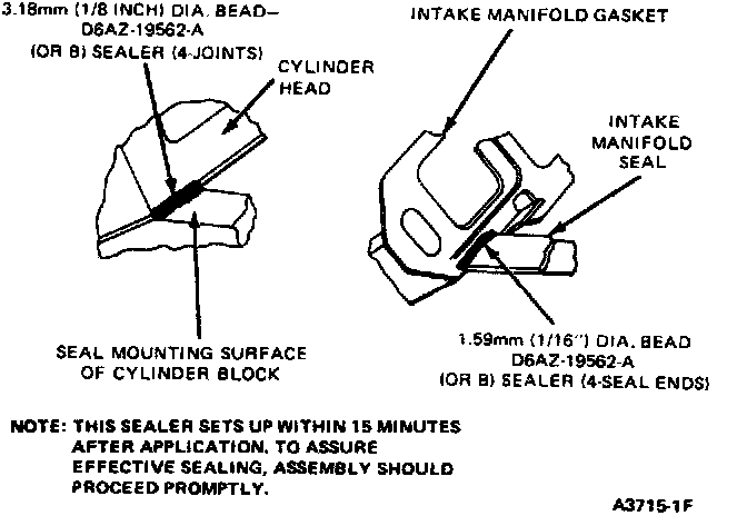
2. Apply 1/16 inch bead of RTV sealer to the end seals (junction).
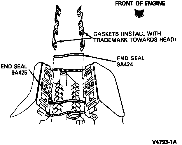
3. Install end seals on the cylinder block and new gaskets on the cylinder heads.
NOTE: The gaskets must be interlocked with the seal tabs.
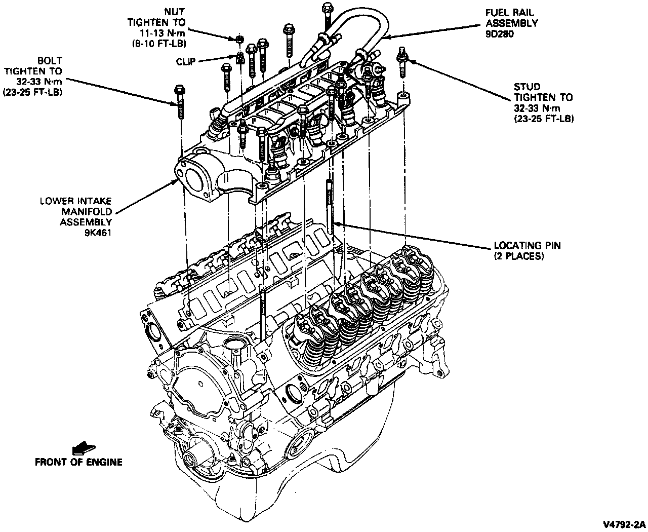
4. Install two locator pins into opposite corners.
5. Carefully lower intake manifold assembly into position.
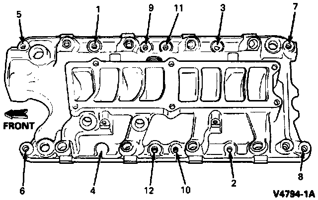
6. Install intake manifold bolts and studs. Tighten all bolts and studs in sequence to 32-33 N-m (23-25 ft-lbs). Wait ten minutes, then tighten all bolts and studs in sequence again to specification.
7. Position coil bracket and hold in place while tightening nut.
8. Install air cleaner bracket to intake manifold studs and exhaust manifold stud. Install attaching nuts and tighten to 19-21 N-m (8-10 ft-lbs).
9. Install upper radiator hose and water bypass hose to thermostat housing.
10. Install heater outlet hose to intake manifold.
11. Connect fuel supply and return lines to fuel rails.
12. Connect the electrical connectors to ECT sensor, ACT sensor, Engine Temperature Sender, and KS.
13. Install distributor assembly in the proper position as noted during removal. Install distributor cap and wires. Check and adjust ignition timing per specification on the engine decal.
14. Install upper intake manifold.
Post-Service Procedures
After the service is complete and the fuel charging assembly is installed to engine, the following steps must be taken:
1. Install fuel cap at tank.
2. Connect negative battery lead.
3. Turn Key ON/OFF several times without starting engine to, check for fuel leaks.
NOTE: Check all connections at fuel rails, push connect fittings, etc.
CAUTION: The fuel system is normally pressurized to 276 kPa (40 psi).
4. Start engine and warm to operating temperature. Check for coolant leak if coolant was removed.
5. Perform Electronic Engine Control (EEC-IV) Self Test to check systems function.