Panel, Instrument: Removal: Removal
 Courtesy of CHRYSLER GROUP, LLC
- Disconnect and isolate the negative battery cable.
- Remove the floor console. Refer to CONSOLE, FLOOR, REMOVAL .
 Courtesy of CHRYSLER GROUP, LLC
- Grasp the fuse access cover (1) from the bottom and pull outward to remove.
 Courtesy of CHRYSLER GROUP, LLC
- Remove the two fasteners (1) from the fuse access area.
- Release the diagnostic terminal (3) from the steering column closeout panel (2).
- Using a Trim Stick (special tool #C-4755, Trim Stick) or equivalent, disengage the retaining clips.
- Remove the steering column closeout (2) from the vehicle.
 Courtesy of CHRYSLER GROUP, LLC
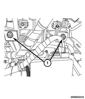
- Remove the two lower steering column mounting fasteners (1).
- Support the steering column with an appropriate device.
 Courtesy of CHRYSLER GROUP, LLC
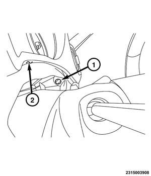
- With the use of a small flat bladed tool or equivalent, remove the center from the retainer (1) located above the steering column.
- With the use of trim remover (special tool #C-4829A, Remover, Trim) or equivalent, remove the retainer (1) securing the cluster bezel and fabric (2) to the instrument panel.
- Repeat on the opposite side.
 Courtesy of CHRYSLER GROUP, LLC
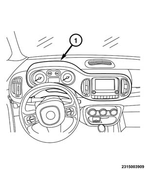
- Using a Trim Stick (special tool #C-4755, Trim Stick) or equivalent, release the cluster bezel (1) retaining clips.
- Raise the steering column into place and loosely install the fasteners
- Remove the radio and radio controls. Refer to RADIO, REMOVAL
.
 Courtesy of CHRYSLER GROUP, LLC
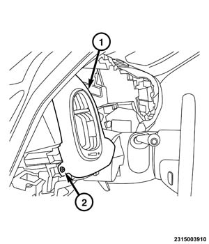
- Remove the fastener (2) from the driver side instrument panel bezel (1).
- Using a Trim Stick (special tool #C-4755, Trim Stick) or equivalent, release the driver side instrument panel bezel (1) retaining clips.
- Remove the driver side instrument panel bezel (1) from the vehicle.
- Remove the instrument cluster. Refer to REMOVAL
.
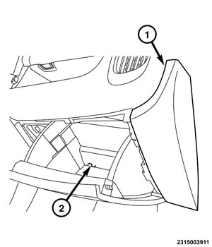 Courtesy of CHRYSLER GROUP, LLC
- Open the glove box door (2).
- Using a Trim Stick (special tool #C-4755, Trim Stick) or equivalent, release right instrument panel end cap (1) retaining clips.
- Remove the end cap (1).
 Courtesy of CHRYSLER GROUP, LLC
- Remove the fasteners (3) from the lower instrument panel bezel (2).
- Open the upper storage bin door (1).
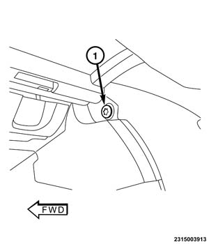 Courtesy of CHRYSLER GROUP, LLC
- Remove the fastener (1).
- Using a Trim Stick (special tool #C-4755, Trim Stick) or equivalent, release the lower instrument panel bezel retaining clips.
- Remove the lower instrument panel bezel.
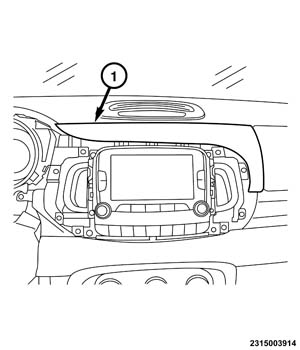 Courtesy of CHRYSLER GROUP, LLC
- Using a Trim Stick (special tool #C-4755, Trim Stick) or equivalent, release the center instrument panel bezel (1) retaining clips.
- Remove the center instrument panel bezel (1) from the vehicle.
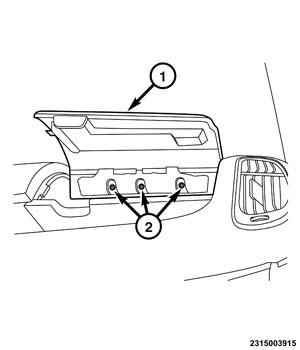 Courtesy of CHRYSLER GROUP, LLC
- Remove the fasteners (2) from the upper storage bin door (1).
- Remove the upper storage bin door (1) from the vehicle.
 Courtesy of CHRYSLER GROUP, LLC
- Remove the two upper fasteners (1) from the HVAC control bezel.
 Courtesy of CHRYSLER GROUP, LLC
- Remove the lower fastener (2).
- Pull rearward on the bezel (1) to release the inner retainers.
 Courtesy of CHRYSLER GROUP, LLC
- Disconnect the wiring connectors from the multi media port (1).
- Remove the HVAC control bezel (2) from the vehicle.
- Remove the heating and air conditioning control. Refer to CONTROL, A/C AND HEATER, REMOVAL
.
 Courtesy of CHRYSLER GROUP, LLC
- Remove the fasteners (1) from the glove box assembly (2).
 Courtesy of CHRYSLER GROUP, LLC
- Disconnect the glove box light switch (3) wiring connector.
- Rotate the glove box assembly (1) rearward and downwards until it is released from the crossmember (2).
- Remove the glove box assembly (1).
 Courtesy of CHRYSLER GROUP, LLC
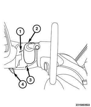
- Using a Trim Stick (special tool #C-4755, Trim Stick) or equivalent, release control trim bezel (2) from the upper (1) and lower (3) steering column shroud.
- Lower the steering wheel position lever (4).
 Courtesy of CHRYSLER GROUP, LLC
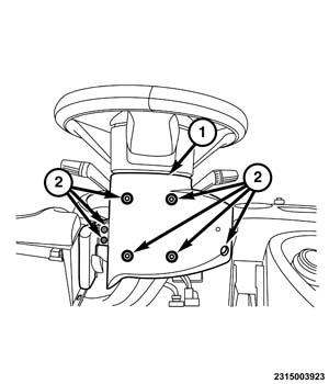
- Remove the fasteners (2) from the steering column shroud. (1).
- Unclip the upper steering column and lower steering column shrouds.
- Route the upper shroud off of the control lever.
- Remove the steering column shroud from the vehicle.
 Courtesy of CHRYSLER GROUP, LLC
- Remove the steering column from the vehicle. Refer to COLUMN, REMOVAL
.
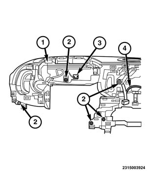
- Remove the fasteners (2) from the left side of the instrument panel cover (1).
- Release the wiring harness retainers (4) for the radio and antenna connections.
- Release the wiring harness retainers (3) in the cluster area.
 Courtesy of CHRYSLER GROUP, LLC
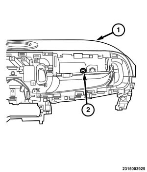
- Remove the fastener (2) from the right side of the instrument panel cover (1).
 Courtesy of CHRYSLER GROUP, LLC
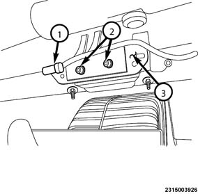
- Disconnect the passenger side air bag wiring connector (1).
- Remove the passenger side air bag bracket (3) mounting fasteners (2).
 Courtesy of CHRYSLER GROUP, LLC
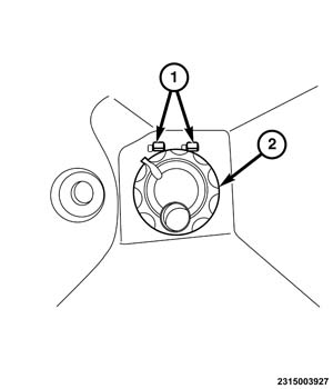
- Within the upper storage bin, remove the air flow adjustment knob (2), with an appropriate tool.
- With the use of a small flat bladed tool, release the retainers (1) for the air flow tube.
 Courtesy of CHRYSLER GROUP, LLC
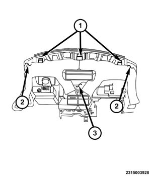
- With the help of an assistant, move the instrument panel cover (3) rearward, releasing the front guides (1) and side guides (2).
 Courtesy of CHRYSLER GROUP, LLC
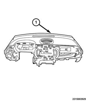
- Remove the instrument panel cover (1) from the vehicle.